
BE-1204C-BC - Uncategorized BROTHER - Free user manual and instructions
Find the device manual for free BE-1204C-BC BROTHER in PDF.


| Product Type | 12-Needle, 4-Head Embroidery Machine |
| Number of Needles | 12 |
| Number of Heads | 4 |
| Sewing Speed | Maximum 1000 rpm |
| Distance Between Heads | 500 mm |
| Maximum Feed Range | 450 (V) × 500 (H) mm; 95 (V) × 360 (H) mm (with cap frame) |
| Sewing Area | 450 (V) × 500 (H) mm (with sash frame); 440 (V) × 400 (H) mm (with max-size tubular square hoop/flat hoop); 85 (V) × 360 (H) mm (with cap frame) |
| Feed System | Timing belt and stepping motor drive |
| Stitch Length | 0.1 to 12.7 mm (minimum pitch 0.1 mm) |
| Storage Media | 3.5-inch floppy disk (Tajima, Barudan, ZSK, Brother ECS formats) |
| Thread Trimming | Automatic |
| Thread Breakage Detection | Upper and lower thread breakage detector |
| Power Supply | Single phase 200 V, 220 V, 230 V, 240 V; 1.1 kVA |
| Power Consumption | 1.1 kVA (machine), 92 VA (fluorescent lamp) |
| Weight | 670 kg |
| Dimensions (Before Assembly) | 2320 (W) × 810 (L) × 1400 (H) mm |
| Dimensions (After Setup) | 2320 (W) × 1360 (L) × 1750 (H) mm |
| Options | Embroidery hoops in different sizes, bobbin winder |
| Included Software | Embroidery Machine Controller, Embroidery Data Explorer, Embroidery Data Editor, Production Report |
| Safety Features | Emergency stop switch, safety devices, warning labels, ground connection required |
| Maintenance Required | Regular cleaning, oiling, greasing; periodic adjustment of needle bar height, rotary hook, and presser foot |
| Operating Environment | Temperature 5°C to 35°C; relative humidity 45% to 85%; avoid direct sunlight and strong electrical noise |
Frequently Asked Questions - BE-1204C-BC BROTHER
User questions about BE-1204C-BC BROTHER
0 question about this device. Answer the ones you know or ask your own.
Ask a new question about this device
Download the instructions for your Uncategorized in PDF format for free! Find your manual BE-1204C-BC - BROTHER and take your electronic device back in hand. On this page are published all the documents necessary for the use of your device. BE-1204C-BC by BROTHER.
USER MANUAL BE-1204C-BC BROTHER
Please read this manual before using the machine.
Please keep this manual within easy reach for quick reference.
TWELVE NEEDLE FOUR HEAD EMBROIDERY MACHINE
TWELVE NEEDLE FOUR HEAD EMBROIDERY MACHINE
TWELVE NEEDLE SIX HEAD EMBROIDERY MACHINE
Thank you very much for buying a BROTHER sewing machine. Before using your new machine, please read the safety instructions below and the explanations given in the instruction manual.
With industrial sewing machines, it is normal to carry out work while positioned directly in front of moving parts such as the needle and thread take-up lever, and consequently there is always a danger of injury that can be caused by these parts. Follow the instructions from training personnel and instructors regarding safe and correct operation before operating the machine so that you will know how to use it correctly.
SAFETY INSTRUCTIONS
1 Safety indications and their meanings
This instruction manual and the indications and symbols that are used on the machine itself are provided in order to ensure safe operation of this machine and to prevent accidents and injury to yourself or other people. The meanings of these indications and symbols are given below.
Indications
 DANGER DANGER | The instructions which follow this term indicate situations where failure to follow the instructions will almost certainly result in death or severe injury. |
 CAUTION CAUTION | The instructions which follow this term indicate situations where failure to follow the instructions could cause injury when using the machine or physical damage to equipment and surroundings. |
Symbols

This symbol ( ) indicates something that you should be careful of.
The picture inside the triangle indicates the nature of the caution that must be taken. (For example, the symbol at left means "beware of injury".)

This symbol ( ) indicates something that you must not do.

This symbol (●) indicates something that you must do.
The picture inside the circle indicates the nature of the thing that must be done. (For example, the symbol at left means "you must make the ground connection".)
2 Notes on safety
DANGER

Wait at least 5 minutes after turning off the power switch and disconnecting the power cord from the wall outlet before opening the face plate of the control box. Touching areas where high voltages are present can result in severe injury.
CAUTION
Environmental requirements

Use the sewing machine in an area which is free from sources of strong electrical noise such as high-frequency welders. Sources of strong electrical noise may cause problems with correct operation.

Any fluctuations in the power supply voltage should be within ±10% of the rated voltage for the machine. Voltage fluctuations which are greater than this may cause problems with correct operation.

The power supply capacity should be greater than the requirements for the sewing machine's electrical consumption. Insufficient power supply capacity may cause problems with correct operation.

The air supply should have a capacity greater than the machine consumption. If air is not supplied sufficiently, a machine malfunction may occur.

The ambient temperature should be within the range of 5^ C to 35^ C during use. Temperatures which are lower or higher than this may cause problems with correct operation.

The relative humidity should be within the range of 45% to 85% during use, and no dew formation should occur in any devices. Excessively dry or humid environments and dew formation may cause problems with correct operation.

Avoid exposure to direct sunlight during use. Exposure to direct sunlight may cause problems with correct operation.

In the event of an electrical storm, turn off the power and disconnect the power cord from the wall outlet. Lightning may cause problems with correct operation.

Do not use this machine outdoors.
Installation

Machine installation should only be carried out by a qualified technician.

Never operate the sewing machine with any ventilation openings blocked.

Keep the ventilation openings of the sewing machine free from the accumulation of lint or dust.

Contact your Brother dealer or a qualified electrician for any electrical work that may need to be done.

The sewing machine weighs approximately 700 kg. The installation should be carried out by four or more people.

Do not connect the power cord until installation is complete, otherwise the machine may operate if the start switch is pressed by mistake, which could result in injury.

Be sure to connect the ground. If the ground connection is not secure, you run a high risk of receiving a serious electric shock, and problems with correct operation may also occur.

When securing the cords, do not bend the cords excessively or fasten them too hard with staples, otherwise there is the danger that fire or electric shocks could occur.

Be sure to wear protective goggles and gloves when handling the lubricating oil or grease, so that no oil or grease gets into your eyes or onto your skin, otherwise inflammation can result. Furthermore, do not drink the oil or grease under any circumstances, as they can cause vomiting and diarrhoea. Keep the oil out of the reach of children.

Secure the machine with the adjustment bolts on the sound floor so that it will not move.
| Installation | |
| Avoid setting up the sewing machine near sources of strong electrical noise such as high-frequency welding equipment.If this precaution is not taken, incorrect machine operation may result. | |
| CAUTION | |
| Sewing | |
| This sewing machine should only be used by operators who have received the necessary training in safe use beforehand.Keep children away from the sewing machine.The sewing machine should not be used for any applications other than sewing.Be sure to wear protective goggles when using the machine.If goggles are not worn, there is the danger that if a needle breaks, parts of the broken needle may enter your eyes and injury may result.Always use the proper needle plate.Any wrong plate can cause needles to break.Do not use a bent needle.Turn off the power switch at the following times, otherwise the machine may operate if the start switch is pressed by mistake, which could result in injury.When threading the needleWhen replacing the bobbin and needleWhen not using the machine and when leaving the machine unattendedWhen cleaning the machine.Do not get on the table.Table may be damaged.Do not operate this machine where aerosol (spray) products are being used or where oxygen is being administered. | Attach all safety devices before using the sewing machine. If the machine is used without these devices attached, injury may result.Do not touch any moving parts, press any objects against the machine, or pull/push the cloth during sewing. Doing so may result in personal injury, machine damage, or needle breakage.Do not touch the pulse motor and sewing machine bed section during operation or for 30 minutes after operation. Otherwise burns may result.Never drop or insert foreign objects or a screwdriver into the ventilation openings or the machine inside.Touching any high-voltage area may result in an electric shock.Never damage, alter, heat, or put a strain on the power cable as well as other cables. Doing so may result in a fire or an electric shock.If the controller is exposed to water or a chemical agent or if its entry is found inside the controller, turn off the power switch immediately.Continuing to use the machine under such a condition may result in a fire or an electric shock.If an error occurs in machine operation, or if abnormal noises or smells are noticed, immediately turn off the power switch. Then contact your nearest Brother dealer or a qualified technician.If the machine develops a problem, contact your nearest Brother dealer or a qualified technician. |
| Cleaning | |
| Turn off the power switch before starting any cleaning work, otherwise the machine may operate if the start switch is pressed by mistake, which could result in injury. | Be sure to wear protective goggles and gloves when handling the lubricating oil or grease, so that no oil or grease gets into your eyes or onto your skin, otherwise inflammation can result.Furthermore, do not drink the oil or grease under any circumstances, as they can cause vomiting and diarrhoea.Keep the oil out of the reach of children. |
Maintenance and inspection

Maintenance and inspection of the sewing machine should only be carried out by a qualified technician.

Ask your Brother dealer or a qualified electrician to carry out any maintenance and inspection of the electrical system.

Turn off the power switch and disconnect the power cable (do not pull on the cable itself) from the wall outlet before attempting to perform the following operations. Otherwise, the machine is started if the start switch is pressed by mistake. Injury may occur in such a case.
- When carrying out inspection, adjustment, or maintenance
- When replacing consumable parts such as a rotary hook, a knife, or a fluorescent lamp

If the power switch needs to be left on when carrying out some adjustment, be extremely careful to observe all safety precautions.

Use only the proper replacement parts as specified by Brother. When replacing a fluorescent lamp, use the same-type lamp having a rating of 40 watts. Wait until the fluorescent lamp cools off before replacement. Failure to do so can result in burns.

If any safety devices have been removed, be absolutely sure to re-install them to their original positions and check that they operate correctly before using the machine.

Any problems in machine operation which result from unauthorized modifications to the machine will not be covered by the warranty.
3 Warning labels
* The following warning labels appear on the sewing machine.
Please follow the instructions on the labels at all times when using the machine. If the labels have been removed or are difficult to read, please contact your nearest Brother dealer.
1 Electric shock danger display

W1408Q
2 Electric shock danger display 3 Injury warning display

Hazardous voltage will cause injury.
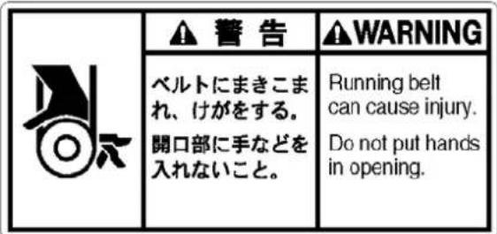
Never touch or push the thread take up during operation as it may result in injuries machine.
7 Injury caution display

Never touch or push the needle bar during operation as it may result in injuries or damage to the sewing machine.
8 High temperature caution display 9 High temperature caution display
| 注意 | |
| CAUTION | ACHTUNG |
| Heated cover may bum hands. Do not touch when operating. | Verbrennungsgefahr! Deckel bei Bedienung nicht ber?hren! |
| ATTENTION | ATENCION |
| Couverde chaud risque de br ler les mains. Ne pas toucher pendant le fonctionnement. | La tapa caliente puede quemarle las manos. No tocar estando en marcha. |
W1201Q

Do not touch this part during activation or for 30 minutes after shut-off. Otherwise burns may result.
10 Ground mark

Be sure to connect the ground. If the ground connection is not secure, you run a high risk of receiving a serious electric shock, and problems with correct operation may also occur.
11 Direction of operation

W1205Q

Do not force open the shutter for direct contact with the magnetic area.

W1209Q
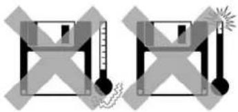
Do not store floppy disks in an extremely high or low ambient temperature.
natural_image
Two identical diagrams showing a thermometer and a spring scale, no text or symbols present.W1211Q
Do not use or store floppy disks in a dusty place. Do not place it on cloth.

natural_image
Two abstract geometric diagrams with shaded regions and dots, no text or symbols presentW1213Q
Do not bend the disk. Do not put things on the disk.

W1215Q
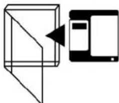
Store it in the case immediately after using it to protect it from dust and damage.
flowchart
graph LR
    A["Input Image"] --> B["Processing Unit"]
    B --> C["Display"]
W1217Q
Do not remove the disk out of the drive during the access lamp is lit.
Do not bring disks near magnetic matters such as magnetic screwdriver or the back side of the programmer.
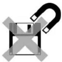
natural_image
Symbol of a floppy disk with a lightning bolt, crossed out by a diagonal line (no text or labels)W1210Q
Do not use floppy disks under high humidity.

W1212Q
Do not store floppy disks under direct sunlight.

W1214Q
Avoid contact with solvent or drink.
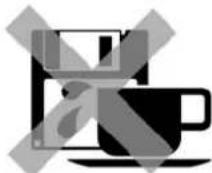
W1216Q
Use a commercially available cleaning disk to clean the head of the floppy disk drive periodically.

W1218Q
Protecting data in floppy disks
Write-protection is available for a floppy disk to prevent undesired data deletion.
A write-protected disk is read-only. It is recommended to provide write-protection for disks which contain important data.
To do so, slide the write-protect notch to open the slot as shown below.

Slide the notch in this direction to prevent data loss or overwriting.
Slide the notch in this direction to write data.
W1219Q
Explanation of models
This manual explains three models:
- BE-1204B-BC
- BE-1204C-BC
- BE-1206B-BC
Explanation for individual model is provided by identifying the model name. Check the model before using the machine. The display is BE-1206B-BC.
Configuration of this manual
This manual consists of the following chapters:
Chapter 1 An Introduction of Embroidery Machine
Provides information on the specifications of the embroidery machine, software installation environment, and basic software operations.
Chapter 2 Preparation of Embroidery Machine
Describes machine installation and preparation to be conducted before starting embroidering operation.
Chapter 3 Embroidering Procedures
Provides explanations on the operation panel and briefly reviews the flow of embroidering processes.
Chapter 4 Selecting and Transferring Embroidery Data
Explains how to use the Embroidery Data Explorer.
Chapter 5 Editing Embroidery Data
Explains how to use the Embroidery Data Editor.
Chapter 6 Embroidering
Explains how to use the Machine Controller.
Chapter 7 Operation of Machine
Provides information on machine operation during embroidering.
Chapter 8 Creating Production Report
Explains how to use the production report program.
Chapter 9 Maintenance
Describes appropriate maintenance of the machine.
Chapter 10 Adjustment
Explains how to adjust the needles.
Chapter 11 List of Error Codes
Provides information on error codes and action to be taken.
Chapter 12 Troubleshooting
Provides troubleshooting for the machine.
Chapter 13 Connection and Installation of Optional Equipment
Describes connections between the machine/computer and optional equipment available.
Contents
SAFETY INSTRUCTIONS ....1
Before Starting Operation 8
Procedure of Reading This Manual....10
Chapter 1 Preparation of Embroidery Machine
- Specifications....1-2
Accessories 1-3
- Software....1-4
2-1 Necessary Systems 1-4
2-2 Configuration of Software....1-4
2-3 Notes on use....1-5
2-4 Help 1-5
2-5 Basic Operation of Software 1-6
Chapter 2 Preparation of Embroidery Machine
-
Names of Machine Components....2-2
-
Installation 2-3
2-1 Transportation of Machine....2-3
2-2 Installation of Machine 2-5
2-3 Preparation of Needle Bar Case 2-6
2-4 Mounting of Table....2-7
2-5 Mounting of Cotton Stand 2-10
2-6 Lubrication to Needle Bar Case 2-11
2-7 Connection of Personal Computer to Machines (for connecting 4 sets) ......2-12
2-8 Connection of Power Supply....2-14
2-9 Grounding 2-15
2-10 Installation of Software....2-16
- Preparation for Embroidering 2-17
3-1 Upper Threading....2-17
3-2 Replacement of Bobbin....2-19
3-3 Replacing and Selecting Needle 2-21
3-4 Attachment of Embroidery Hoop and Frame 2-22
3-5 Adjustment of Thread Tension....2-26
Chapter 3 Embroidering Procedures
Functions of Operation Panel....3-2
Operation Panel 3-2
Switches at Machine Heads....3-4
Lamps and switches on the thread tension stand 3-5
Flowchart of Preparation for Embroidering....3-6
Run the Software 3-7
Turn on the Machine Power 3-7
Register the Machine Name....3-8
Retrieve the Embroidery Data....3-8
Start Embroidering 3-9
Chapter 4 Selecting and Transferring Embroidery Data
Functions (Command Reference) 4-2
Description of Screen 4-3
Creating a Directory 4-4
Transferring data 4-5
Copy 4-7
Select from Menu....4-7
Drag Data 4-7
Moving Data 4-8
Select from Menu....4-8
Drag Data 4-8
Deleting Data....4-9
Recreate an icon....4-10
Select All 4-11
Renaming Data 4-12
Finding Data 4-13
Adjusting Screen Display 4-15
Reading Data in Floppy Disk 4-16
Reading DOS Format Data....4-16
Converting the Non DOS format data....4-18
Reading Data in Paper Tape 4-22
Settings for Data Reading....4-24
Writing Data in DST Format 4-25
Viewing Pattern Information....4-26
Chapter 5 Editing Embroidery Data
Functions (Command Reference) 5-2
Description of Screen 5-4
Opening Embroidery Data 5-5
Setting Display....5-6
Centering 5-6
Zoom 5-6
Needle Penetration....5-8
Embroidering Start/End....5-8
Trim and pause....5-8
Microstitch 5-9
Needle Bar and Speed Range 5-9
Thread Color....5-13
Tool bar....5-14
Status Bar 5-14
Back to Previous Status....5-15
Undo 5-15
Redo 5-15
Editing 5-16
Rotate 5-16
Horizontal Flip....5-17
Vertical Flip 5-17
Point Symmetry 5-17
Repeat....5-17
Resize....5-20
Delete Stitch 5-20
Insert or Delete Code....5-21
Insert Lock Stitch 5-22
Changing Data....5-23
Changing Start 5-23
Changing End 5-24
Mask 5-25
Group 5-26
Setting Group for Repetition....5-27
Selecting from Menu 5-27
Merge 5-28
Saving Data 5-30
Save 5-30
Save As....5-31
Viewing Pattern Information 5-32
Printing Data....5-33
Chapter 6 Embroidering
Functions (Command Reference)....6-2
When the Power to the Machine is Off....6-2
When the Power to the Machine is On....6-2
Description of Screen....6-5
Settings before Turning On the Machine....6-6
Displaying the Tool Bar 6-6
Displaying the Status Bar 6-7
Upgrading the Version of Interface Board 6-7
Reset Interface Board 6-7
Communication Port....6-7
Language 6-8
Settings after Turning Power On 6-9
Tool Bar....6-9
Status Bar 6-9
Zoom In....6-9
Zoom Out....6-9
Zoom In Specified Range....6-10
Fit to Window 6-10
Whole Pattern 6-10
Grid 6-11
Hoop 6-11
Hoop position fine adjustment....6-11
Needle Penetration 6-12
Thread Color....6-13
Needle Bar and Speed Range 6-13
Setting Needle Bar....6-13
Setting Ranges 6-17
Grid Setting....6-18
Background color 6-18
Renaming Machine 6-19
Viewing Machine Information 6-20
Design Information....6-20
Setting Window Display 6-20
Minimizing and Aligning Windows....6-21
Language 6-23
Copying Data to Other Machines 6-23
Configuration....6-24
Upgrading the Machine Program 6-24
Setting the Machine....6-25
Needle Bar....6-25
Same Speed Range 6-26
Pause 6-26
Speed Range 6-27
Head Operation Suspend 6-27
Hoop Feed Position 6-28
Embroidery Area....6-29
Embroidery Hoop....6-29
Thread Trimming 6-31
Thread Breakage Sensor....6-32
Automatic Step Back 6-33
Automatic Hoop Feed 6-33
End of embroidery 6-34
Mending....6-35
Adjust....6-36
Driving shaft....6-37
Activate escape with pause 6-37
Short stitch speed reduction 6-38
Thin / Thick Material 6-39
Area Trace 6-40
Trace with needle No.1 6-40
Default Settings 6-41
Show Setting 6-42
Load Setting 6-44
Save Setting 6-45
Load Hoop....6-46
Embroidering 6-50
Starting Embroidering 6-50
Moving the Home Position 6-52
Step-forward/Step-back 6-53
Entering in the Step-forward/Step-back Mode 6-53
Setting Step-forward/Back Distance or Timing....6-54
Stepping Forward/Back....6-55
Resuming Embroidering 6-56
Moving Embroidery Position 6-57
Centering Pattern 6-58
Saving Data 6-59
Save 6-59
Save As....6-59
Test 6-60
Running Other Programs....6-61
Chapter 7 Operation of Machine
1. Operating Procedures 7-2
1-1 Power Source 7-2
1-2 Preparation for Embroidering....7-2
2. Machine Stop....7-3
2-1 Stopping the Machine 7-3
2-2 Emergency Stop of the Machine 7-3
2-3 Resetting Emergency Stop 7-3
3. Permission for Hoop Movement....7-4
4. Measures against Thread Breakage....7-5
4-1 Remedies....7-5
4-2 Mending....7-6
5. Jog Embroidering....7-8
6. Hoop Feed Position 7-9
7. Area Check 7-10
7-1 External Tracing....7-10
7-2 Automatic Hoop Movement in Area....7-10
8. Jog Switches....7-11
8-1 Hoop Movement to Start Position....7-11
8-2 Inching Mode during Embroidering (Forcible Hoop Movement)....7-12
Chapter 8 Creating Production Report
Functions (Command Reference)......8-2
Description of Screen....8-3
Displaying Report 8-4
Display Example of Details 8-5
Display Example of Thread Breakage Information on Needle Bar 8-6
Display Example of Thread breakage Information in Pattern 8-7
Display Example of Output Information....8-8
Display Example of Total Output Information 8-10
Setting Display Items....8-12
General 8-12
Details 8-13
Thread Breakage Information on Needle Bar....8-14
Thread Breakage Information in Pattern....8-14
Output Information 8-15
Total Output Information 8-16
Recess Time Setting 8-17
Save As CSV....8-18
Printing Production Report....8-19
Page Setup 8-19
Print....8-19
Copying Report Data 8-20
Chapter 9 Maintenance
- Cleaning 9-2
1-1 Cleaning and Lubrication of Rotary Hook....9-2
1-2 Cleaning of Needle Plate....9-3
- Oiling 9-4
2-1 Head....9-4
2-2 Lower shaft....9-5
- Greasing....9-6
3-1 Cam grooves 9-6
3-2 Lower gear 9-8
3-3 Driving shaft....9-8
3-4 Needle bar flip-up mechanism....9-9
3-5 Feed Guide Section....9-10
Chapter 10 Adjustment
- Adjusting Needle Bar Height 10-2
- Attachment and Adjustment of Rotary Hook....10-6
- Adjustment of Presser Foot Height....10-8
- Thread Wiper Adjustment....10-9
Chapter 11 Error code list
Chapter 12 Troubleshooting
Mechanical Section 12-2
Electrical Section....12-4
Personal Computer Section 12-8
Chapter 13 Connection and Installation of Optional Equipment
- Attaching Bobbin Winder....13-2
Chapter 1
An Introduction of
Embroidery Machine
- Specifications
| Embroidery machine used | 12 needle six-head embroidery machine | 12 needle four-head embroidery machine | 12 needle four-head embroidery machine |
| BE-1206B BE-1204B BE-1 | 204C | ||
| Application Pattern embroidery | |||
| Sewing speed Maximum 1000 rpm | |||
| Distance between heads 360 mm 500 mm | |||
| Maximum feed range | 450 (V) × 360 (H) mm95 (V) × 360 (H) mm (With cap frame) | 450 (V) × 500 (H) mm95 (V) × 360 (H) mm (With cap frame) | |
| Sewing area | 450 (V) × 360 (H) mm (With sash frame)430 (V) × 300 (H) mm (With maximum-size tubular square hoop/flat hoop)85 (V) × 360 (H) mm (With cap frame) | 450 (V) × 500 (H) mm (With sash frame)440 (V) × 400 (H) mm (With maximum-size tubular square hoop/flat hoop)85 (V) × 360 (H) mm (With cap frame) | |
| Feed system By timing belt and stepping motor drive | |||
| Stitch length 0.1 ~ 12.7 mm | (minimum pitch: 0.1 mm) | ||
| Storage medium | 3.5 2DD floppy disk (Tajima format)3.5 2HD floppy disk (the equivalent to Tajima format)3.5 2DD floppy disk (Barudan FDR/FMC format)3.5 2DD floppy disk (ZSK format)3.5 floppy disk (brother ECS format) | ||
| Thread trimming Automatic thread trimmer | |||
| Thread breakage detect Upper and lower thread breakage detector | |||
| Power supply | Single phase 200 V, 220 V, 230 V, 240 V,1.1 kVAFlourescent lamp: 92VA 49W (Maximum) | ||
| Weight 700 kg | 600kg | 670kg | |
| Dimensions | (Before assembly)3040 (W) × 810 (L) × 1400 (H) mm(After setup)3040 (W) × 1360 (L) × 1750 (H) mm | (Before assembly)2320 (W) × 810 (L) × 1400 (H) mm(After setup)2320 (W) × 1360 (L) × 1750 (H) mm | (Before assembly)3040 (W) × 810 (L) × 1400 (H) mm(After setup)3040 (W) × 1360 (L) × 1750 (H) mm |
| Options | Embroidery hoops in different sizes, Bobbin winder | ||
2. Software
2-1 Necessary Systems
The following systems are needed for installing the software.
- Personal computer with a CPU of Intel Pentium 166 MHz or above
(Even if the software is operable under the environment less than the required specification, such a case is out of the scope of warranty.) - Memory of 32 MB or above (Even if the software is operable under the environment less than the required specification, such a case is out of the scope of warranty.)
• Free space of 100 MB or above in the hard disk
• 3.5 floppy disk drive - CD-ROM drive
• Video card of 1024 × 768 resolution in 256 colors
(1280 × 1024 in 65000 colors is recommended.) - Serial port (RS-232C) × 1
- PCI slot × 1
(Use full-size type PCI slot. Low profile type and half pitch type cannot be used.) - Windows 95/98/2000/NT4.0/XP (Some functions are not available with Windows NT. Refer to page 4-18.)
2-2 Configuration of Software
This software is mainly composed of the following four programs. The software is provided on CD-R.
(1) Embroidery Machine Controller
(2) Embroidery Data Explorer
(3) Embroidery Data Editor
(4) Production Report
Program Functions
(1) Machine Controller
This program controls embroidering operation of the machine.
A embroidering status can be displayed on the screen in real time, and data for operating the machine can be set.
(2) Embroidery Data Explorer
This program handles files of embroidery data on patterns.
Transmission of embroidery data to the machine, as well as copy, move and retrieval of a file are available by means of this program. Embroidery data can be converted from the paper tape or floppy disk.
(3) Embroidery Data Editor
This program allows editing of data on embroidering operation including scaling, rotation, color change, etc.
(4) Production Report
This program is for collecting data on actual embroidering operation and calculating output, etc.
Relationship among Programs
When the software is started, the program (1) for actuating the machine starts first.
Next, embroidery data is called by the program (2). Use the program (3), when required, for editing and embroidering. The embroidery data is totaled by the program (4).
The programs (2), (3), and (4) can be started from the menu of the program (1). Each program can also be started independently.
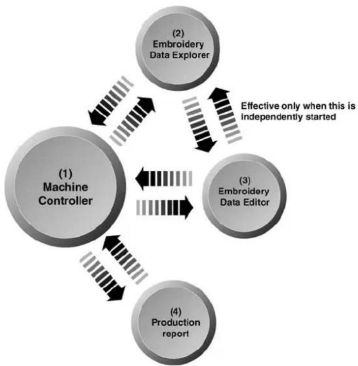
flowchart
graph TD
    A["Machine Controller"] --> B["(2) Embroidery Data Explorer"]
    A --> C["(3) Embroidery Data Editor"]
    A --> D["(4) Production report"]
    B -->|Effective only when this is independently started| E
    C -->|Effective only when this is independently started| F
    D -->|Effective only when this is independently started| G
W1357Q
2-3 Notes on use
- Do not start other application software while the machine controller is used.
- Do not set the screen saver.
To cancel setting, select the "Screen saver" on the "Control panel" screen and set "Not used".
- Set the computer not to use the system agent included in the Windows 95 PLUS.
2-4 Help
The software is equipped with an on-line help function as an accessory.
Click 🔒, then the icon of the desired item. A message is displayed to explain the meaning and usage of the item. Pressing the [F1] key brings up the help screen of the application for your reference.
2-5 Basic Operation of Software
This section explains the basics of using the software. It covers only the operating procedures that are commonly used for the software. If there are any special operating procedures inherent to a program, they are explained in each section.
How to Use the Mouse
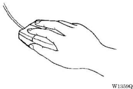
When selecting an icon or a menu displayed on the screen, move the white arrow pointer on the screen to the required position, then press the button on the mouse.
natural_image
Black-and-white line drawing of a potted plant with slender leaves and a mesh basket (no text or symbols)Place the mouse on a flat, smooth surface and move it by sliding on it. The white arrow pointer moves along the mouse motion.
natural_image
Line drawing of a hand holding a computer mouse (no text or symbols)The mouse has two buttons. The left one is used in general. There are three ways of operating the mouse button as described below:
Click
Press the left button of the mouse once.
"Click [xx]" means moving the white arrow pointer to "xx" and pressing the left button once.

natural_image
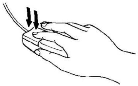
Line drawing of a hand holding a pen or tool, with a black arrow pointing to the pen tip (no text or symbols present)■ Double-click
Press the left mouse button twice continuously. Do not leave a long pause in between.
"Double-click [xx]" means moving the white arrow pointer to "xx" and pressing the left button twice continuously.
natural_image
Line drawing of a hand holding a thin object with two arrows pointing downward (no text or symbols)W1361Q
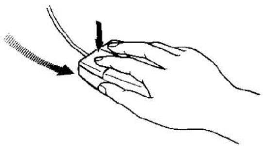
Drag
Move the mouse while holding down the left button. Dragging is used for defining an area.
natural_image
Line drawing of a hand holding a tool with an arrow indicating direction (no text or symbols)W1362Q
Names of Screen Components
Names of major components on the screen of the machine controller are described below:

■ Menu
Processing of software is carried out by giving relative commands.
Commands are divided in groups and stored in each menu. The menu displayed on the screen changes depending on the program which is currently active.
■ Tool bar
A command is executed by clicking a relative icon (illustrated button) on the screen. If it is hard to recognize icons from illustrations, move the white arrow pointer to the icon. The name of the icon is displayed.
■ Scroll bar, scroll box, and scroll arrow
Some patterns may not be displayed entirely on the screen. Use the scroll bar to see hidden parts of the pattern into view.
When displaying the right part, for example, click the scroll arrow at the right end. The box in the scroll bar moves to the right. By dragging the scroll box to the right, the screen can scroll quickly. The vertical scroll bar can be used in the same way.
■ Status bar
This bar is for displaying a brief description of the selected command.
Selection of Menu
Processing of software is carried out by giving a command. A command can be given by the mouse as described below:
- Move the arrow pointer to a menu name and click there.

W1364Q
- A list of commands is displayed. Click the required command.

The check mark (√) indicates that the command is selected.
W1117Q
When the arrow pointer is moved to another menu while a list of commands is displayed, those of the latter menu are displayed.
Chapter 2 Preparation of Embroidery Machine
1. Names of Machine Components
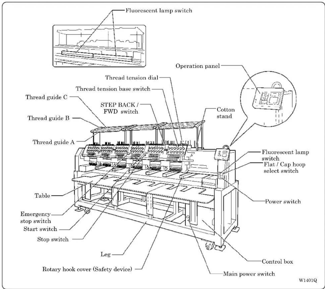
The machine heads are numbered 1 to 6 (1 to 4 in four head models) from the right front.
2. Installation
!DANGER

Embroidery machines should be installed only by trained engineers.

Electric wiring should be laid by your distributor or electric experts.

The sewing machine weighs approximately 700 kg. The installation should be carried out by four or more people.

Do not connect the power source until installation is completed. Doing so may start the machine unintentionally through an accidental activation of the START switch, resulting in bodily injuries.

Install a machine in a place away from a high-frequency welding machine or other machines that may generate a strong electric noise. Failure to do so may cause the embroidery machine to malfunction.

Be sure to connect the ground. If the ground connection is not secure, you run a high risk of receiving a serious electric shock, and problems with correct operation may also occur.

Secure the machine with the adjustment bolts on the sound floor so that it will not move.
After installation is completed, get the power supply from a dedicated outlet.
When connecting multiple machines, exercise care not to exceed the capacity of the outlet.
2-1 Transportation of Machine
When relocating the machine, push the steel frame. Never push the cover or carriage.
■ When using a fork lift

W1222Q
- Viewing the machine from the back, position their center at the central seal, insert the forks under the legs and lift the machine.
■ When using a crane

- Hook on the eyebolts with each belt to lift up the machine.
When lifting the machine, make sure that the belts do not contact the machine table or the tension plate.
2-2 Installation of Machine
![[5] [1] [4] [3] [2]](/content/2026/05/1004755/images/001d62252de62b7195899073a15744e8d03559f3f531b15f36c6e8d2f64e8c0b.jpg)
W1224Q
-
Place Footboard [4], a rubber cushion 10 [3] (provided with the machine), and PE sheet [2] under each of four adjustment bolts M20 [1]. The Footboard must be on the rubber cushion.
-
Fit four adjustment bolts M20 [1] into the hole of Footboard [4], and adjust the embroidery machine in height.
The adjustment must be made in such a manner that the four bolts are under an equal load when the machine is placed down. (To lower adjustment bolt M20 [1], turn it in the direction of the arrow.) Also, the casters should be raised.
- After adjusting four adjustment bolts M20 [1], turn nuts M20 [5] in the direction of the arrow to fasten them.
If the floor is not strong enough, the embroidery machine may be rocked during operation. In such a case, it is recommended that a secure base of concrete be placed below the embroidery machine.
2-3 Preparation of Needle Bar Case
![[1] [2] [3]](/content/2026/05/1004755/images/852200233f41b5b5b7f387fb3e4423a32933e095bb40a412c7cd35f2058de971.jpg)
W1225Q
Repeat the procedures below for all the heads:
- Unscrew the screw [1], then detach the bracket [3] and pin [2].
2-4 Mounting of Table
■ Preparation for mounting the table
![Table guide bridge [1] W1226Q](/content/2026/05/1004755/images/24593cfc7a149915766360cd1f786003f6664b21f6233a15abc97eaf3af19672.jpg)
-
This operation is required only when the table set is purchased separately from the machine.
• The table is a standard attachment. -
Tentatively mount 4 (3 in BE-1204B) table supports Front [1] on the leg front using 4 bolts each.
■ For embroidering with tubular square hoop or cap frame (lower position)
![[7] [6] [4] [5] [8] [3] [2] [1] [5] W1227Q](/content/2026/05/1004755/images/4e09bd3f31023a8f86ad89710b43fa6590f9610d2b8fddc7167f337f879d135a.jpg)
- Attach four hexagon socket head cap screws to each of table parts R [1], M 2, and L [3] from the back.
- Put the table backing plate [4] of each table on to the table guide bridge [5], and slide to the other side. Insert the table backing plate [4] into the table backing rubber on the table support Rear [6].
- Adjust table supports front [7] in height so as to make the table parallel with the floor.
- Tighten all hexagon socket head cap screws [8] firmly.
■ For embroidering with flat hoop/sash frame (upper position)
![[5] [4] [2] [3] [1] [7] [6] W1228Q](/content/2026/05/1004755/images/9dbd69a705d89cea3e73f2344410ec612312187cf5af25bc9ee7de16a7ac2cfc.jpg)
- Attach four hexagon socket head cap screws to each of table parts R [1], M 2, and L [3] from the back.
- Insert the table backing plate [4] of each table into the table backing rubber on the table support Middle [5].
- Adjust the height of the table support Front [6] to be even with the upper surface of the bed.
- Tighten all hexagon socket head cap screws firmly.
- Attach four (three in BE-1204B) thumb bolts to the lower front steel pipe of the leg section. Fasten the table and the leg section using table stays (4 pcs(3 pcs in BE-1204B)) [7].
2-5 Mounting of Cotton Stand
![Thread guide A Thread guide B Thread guide C [5] [4] [3] [6] Front [1] [2]](/content/2026/05/1004755/images/18cbe6885b69d9f2db572331c3a195e1db85338d76af4969e941273bc28537e6.jpg)
W1229Q
- Attach the cotton stand bars [2] to the cotton stand [1].
- Attach six thread guide support bars [3] to the cotton stand [1], while fitting into the six holes.
- Mount the thread guide assembly [4] on the thread guide support bars [3] using the six screws [5].
- When mounting, use one flat washer [6] below the thread guide support bar [3].
- Pay careful attention to the front and back directions of the thread guides (A, B, C).
2-6 Lubrication to Needle Bar Case
Proper lubrication is necessary for keeping the machine head in good condition.
CAUTION

Turn off the power switch before starting any cleaning work, otherwise the machine may operate if the start switch is pressed by mistake, which could result in injury.

natural_image
Technical line drawing of a mechanical assembly with a tool inserted into a component (no text or symbols)W1221Q
Before operating the machine for the first time after unpacking or after leaving the machine without operation for a long period of time, supply one or two drops of oil to each needle bar from the oil supply holes of the lower cover.
- Use the Brother's specified oil (Nippon Oil, Embroidery Lube 10N; VG10) for this.
* If this type of lubricating oil is difficult to obtain, the recommended oil to use is. - Supplying an excessive amount of oil will cause dripping onto the material.
2-7 Connection of Personal Computer to Machines (for connecting 4 sets)
Be sure to ground the personal computer.
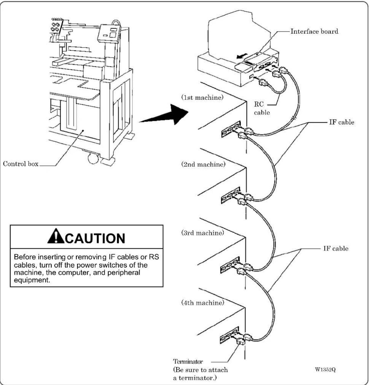
flowchart
graph TD
    A["Control box"] --> B["(1st machine)"]
    B --> C["RC cable"]
    C --> D["IF cable"]
    D --> E["(2nd machine)"]
    E --> F["(3rd machine)"]
    F --> G["IF cable"]
    G --> H["(4th machine)"]
    H --> I["Terminator\n(Be sure to attach a terminator.)"]
- Turn off the power of the personal computer and the machine.
- Open the cover of the personal computer and insert an interface board into the slot for the PCI bus.
- Connect the interface board male connector and the personal computer RS-232C connector (COM1 or RS-232C-1) using the attached short RS cable.
-
Remove the side cover of the control box.
-
Pass the IF cable from the crevice between the frame of leg and the control box.

natural_image
Technical line drawing of a mechanical device with attached cable and mounting bracket (no text or symbols)W1354Q
- Connect the interface board female connector and the control box connector SBUS1 of the first machine using an IF cable.

W1353Q
-
Connect the control box connector SBUS2 of the first machine and the control box connector SBUS1 of the second machine using an IF cable.
-
Attach the side cover of the control box.
-
Connect the control box connector SBUS2 of the second machine and the control box connector SBUS1 of the third machine using an IF cable.
-
Connect the control box connector SBUS2 of the third machine and the control box connector SBUS1 of the forth machine using an IF cable.
-
Attach a terminator to the control box connector SBUS2 of the forth (last) machine.
-
The IF cables used for connection are identical. There is no difference between the two ends of the IF cable.
• The order of connecting four machines is arbitrary.
• The maximum number of connecting machines is four. - A terminator should be connected to the connector SBUS2 of the lastly connected machine. Connection to SBUS1, 2 can be interchangeable.
2-8 Connection of Power Supply
■ Uninterruptive power supply
This unit is for protecting a personal computer from commercial power interruption, voltage drop, and external noise. Use of an uninterruptive power supply is strongly recommended.
- This unit is not an attachment of the Brother's embroidery machine, and should be purchased separately from a different source.
- When using an uninterruptive power supply, be sure to establish grounding.

2-9 Grounding
CAUTION

Perform a grounding cable connection. Failure to do so may result in electric shock or machine malfunction.
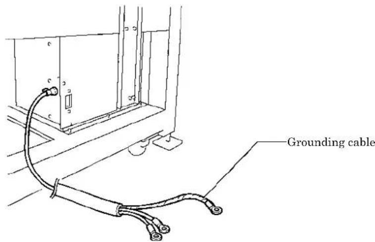
W1231Q
When connecting the power supply, make sure to connect it to the grounding cable (with green and yellow stripes). When plugging in the outlet, use a plug suited to the outlet.
2-10 Installation of Software
Use an attached CD-R for installing software. If a personal computer with no CD-R drive unit is used, connect a drive unit to the computer.
- Set the CD-R for installation.
Setting the CD-R starts the installation program automatically.
- Select the language and click "Next".

W1366Q
- The screen for user registration is displayed. Input your name and department. Click [OK] after inputting is finished.
- Check the user information. Click [OK] if the contents are correct.
- Specify a folder for setup.
- Click [TO NEXT] to start installation.
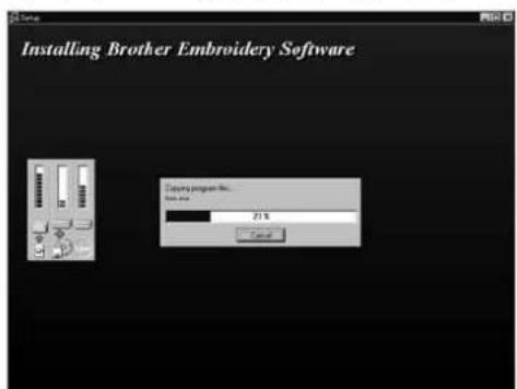
W1367Q
- After setup is properly finished, a message is displayed.
- Click [OK] to complete installation.
3. Preparation for Embroidering
CAUTION

Turn off the power switch before starting preparation.
Failure to do so may start the machine unintentionally through an accidental activation of the START switch, resulting in bodily injuries.
3-1 Upper Threading
![[1] [2] Thread Guide tension disc [3] Tension stand inner thread guide Rotary disc Spring [4] Tension stand lower thread guide Inner thread guide [5] Lower thread guide [6] Needle bar thread guide Pressure foot W1232Q W1233Q](/content/2026/05/1004755/images/313066cf2cf2896e214e0eeb432cb8769d6a6923c63049cdcee5610332be1e92.jpg)
- Pass an upper thread from the cotton stand through the hole of the thread guide right above each cotton stand bar. Pass the thread from the back to the front hole.

Front
W1234Q
- Pass the thread through the upper hole of the pretension [1]. Push up the thread guide tension disc with your finger, and pass it from the left to the lower hole.
- Pass the thread through the upper hole of the 2nd pretension. Push up the thread guide tension disc[2] with your finger, and pass it from the left to the lower hole.
- Wind the thread clockwise once around the rotary disc and place it on the spring.
- Pass the thread through the hole of tension stand inner thread guide [3].
- After passing the thread through the hole of tension stand lower thread guide [4], insert the thread into the right side of the inner thread guide and pass it through the hole of the thread take-up.
- Bring the thread back to the inner thread guide. Insert the thread into the hole from the upper section.
- Pass the thread through the hole of the wire of the needle bar thread guide [6] and pass it through the needle eye. Pass it through the presser foot. Pass it to presser spring at the front of lower thread guide [5].
3-2 Replacement of Bobbin
Remove dust, lint and oil from the bobbin case before replacement.
■ Removing bobbin case
![[2] [1] [3]](/content/2026/05/1004755/images/479451f0245a9e6e93313c45a460e7543d765677a4a1bc864f3e6fe7cffe4df1.jpg)
W1235Q
- Open the rotary hook cover [1].
- Hold the knob [2] and take out the bobbin case.
- Close the knob and take out the bobbin [3].
■ Replacing bobbin

natural_image
Line drawing of hands holding a small mechanical component (no text or symbols)![[4] [5]](/content/2026/05/1004755/images/37283341d35c77b5cc18d9288905cb92c1cc2bc05e54d51d18d1f0db29c844b1.jpg)
W1238Q W1239Q W1240Q
Pull out by about 50 mm
![about 50 mm [5] [6]](/content/2026/05/1004755/images/df192abaaf9168d810ebbe712caa96a03dafc5cda8c4920a188dc7dfee0e03e1.jpg)
1. Put a new bobbin in the bobbin case.
Check the winding direction.
Check that the bobbin is pushed out of the bobbin case by about 0.5 mm. If not, the slip prevention spring of the bobbin case does not work. Adjust the height of the spring or replace it with a new one.

W1237Q
- Slide the thread under the tension spring [5] through the notch [4].
- Pull out the thread from the hole of the tension spring [5].
- Pull out the thread by about 50 mm.
- Pass the thread through the thread guide [6].
■ Attaching bobbin case
![[2] [1] W1241Q](/content/2026/05/1004755/images/ee55b00ec9c0fcca0564df0a9a4b6eece009c4bbe8042294e94f4f2682bd58e9.jpg)
- Hold the knob [2] and attach the bobbin case securely.
- Close the rotary hook cover [1].
3-3 Replacing and Selecting Needle
* Relationship between materials and needles
| Material Needle thickness | ||
| Denim Leather | #1DB × K5 | #14, #16, #18 |
| Handkerchief #9 | ||
| Shirt Towel | #11, #12, #13 | |
■ Selecting needle
- When using special threads such as gold, silver, and rame yarn, use a heavy-duty needle (#11\~#16). For better finish, paste the waxed paper on the back of the material.
- In general, use DB×K5 #11 \~ #18 according to the material thickness. For knitted materials, use DB×K23 #11 because its rounded point prevents the knit thread from breaking.
![[1] [2]](/content/2026/05/1004755/images/0a6f9a48dc10fe7cfc21adf775069c637998a1798c7114390c41a413597ab6e6.jpg)
W1242Q
■ Removing needle
Loosen the set screw [1] and remove the needle [2].
■ Attaching needle
With the flat side facing the front, insert the needle all the way until it meets the end of the needle bar. Tighten the set screw [1] firmly.
- Set the needle so that the notched part will come on the rotary hook side.
- The needle should not be angled to the left (when viewed from the front).
3-4 Attachment of Embroidery Hoop and Frame
■ Tubular square hoop
BE-1204B,BE-1206B
![[1] [4] [2] [2] [3] [5] W1243Q](/content/2026/05/1004755/images/038acbd0d0fd67c300b9139d4cecd3f89bb0388b1ffc8506df7af5c0d1fed35a.jpg)
- Loosen the thumb bolt M6 [1] to draw it to the center.
- Align the positioning hole on the tubular round arm frame [4] with the positioning pin [3] (S58665) on the X-feed sash [5] (S58650), and fit the tubular round arm fixing nut [2] on the back side of the thumb bolt M6 [1] into the hole on the X-feed sash.
- While keeping the nut in the hole, slide the thumb bolt M6 toward the edge and tighten it firmly at the outermost point.
BE-1204C
![[6] [5] (1) (2) (3) [7] [4] 2843M](/content/2026/05/1004755/images/cf5e5abe7d84404f128198fb8990d0ff8952376c11be9526dc826661fec04919.jpg)
The frame is fixed to the position of (1) for 360 pitch, so is to (2) for 400 pitch and to (3) for 500 pitch.
- The tublar round arm frame R [4] is fixed with the thumb bolt [5] to the connecting plate [6] to align with each pitch. At the same time, put the positioning pin [7] into a hole at the center of the tublar round arm frame R [4].
![[10] [9] [10] (1) (2) (3) [8] (3) (2) (1) [4] 2844M](/content/2026/05/1004755/images/a573a86099fea0cec99ded413a33def5421525cc941dc03d12e544e530187e3b.jpg)
- Insert the grooves of the tublar round arm frame L [8] and R [4] onto the thumb bolt M6 [10] on the X-feed sash [9] so as to align with each pitch and fix them.
■ Holder base (optional)

Attaching the holder base frame
- Set the table. (Refer to "Mounting of Table" on page 2-7.)
- Insert the frame connecting plate F [4] into the holder base frame L [1], flat frame C6-360 [2] and holder base frame R [3], using bolts and washers.
[When using the machine only with the holder base frame (small)]
Attach the flat frame S connecting plates L [5] and R [6] to the flat frame S6-360 set [7].
Attach the flat frame S connecting plates L [5] and R [6] to the holder base frames L [1] and R [3], using bolts of 4×12 and washers of middle 4.
-
Remove 4 bolts [9] from the front of X-feed sash [8].
-
Put the frame connecting plates L [10] and R [11] on the X-feed sash [8]. Fix them with bolts and washers.
-
Check that the clearance between the mounted flat frame C6-360 [2] and the table is even when viewed from the machine front.
If adjustments are needed, loosen bolts of the F table support Front [12] and move it in the direction of the arrow.
- Tighten each bolt securely after the adjustment is completed.
Attaching the holder base
- Mount the holder base vertically to the X-axis feed sash [1] and flat frame C6-360 [2] using the thumb bolts [3].
![[3] [1] [3] [2]](/content/2026/05/1004755/images/ca8762c8e6038ccacba0a9cf98cabff723f70aaf11f005023e2ecf70c486cd6f.jpg)
W1246Q
■ Sash frame (optional)

W1247Q
Attaching the sash frame
- Set the table. (Refer to "2-4 Mounting of Table" (Page 2-7) for details.)
- Mount two vertical sash frames [1] on the holder base frames L and R, and two horizontal sash frames [2] on the X-axis feed sash [3] and the holder base frame C6-360 [4], using the screws.
- Set the material. Then set sash clips 290 [5] horizontally and set sash clips 220 [6] vertically. BE-1206B, BE-1204C: Sash clips 290 12 units, sash clips 220 10 units BE-1204B: Sash clips 290 10 units, sash clips 220 6 units
3-5 Adjustment of Thread Tension
■ Adjustment of upper thread

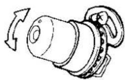
natural_image
Mechanical component diagram showing a rotating shaft and housing with directional arrows (no text or symbols)W1248Q W1249Q
natural_image
Simple line drawing of a plant with leaves and stem, no text or symbols present
Lower stitch width
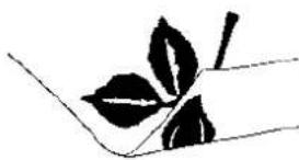
Adjust upper thread tension to 0.8\~1.4N when the thread is pulled at the needle bar thread guide.
\* Correct adjustment
Turn the upper thread tension dial so that the needle thread can be pulled to the back of the material and that the lower stitch width will be about 1/3 of the upper stitch width.
■ Adjustment of tension spring
![[1] 6~8mm 14mm](/content/2026/05/1004755/images/ce4e9a0a6f4bfe4fa8d8837bfe1b8af04f5ad07fcb0a87d796bc7a1e6823d7fe.jpg)
![[2] [3] 0.2~0.3N](/content/2026/05/1004755/images/bf861a770913e1175a1da3982f18f633004c7ed77bb1c88bea5b837413c38d0f.jpg)
W1250Q
- The standard height of the tension spring is the point from where the upper thread comes down by about 14 mm when it is pulled with certain tension which does not pull out the thread.
-
The standard force of the tension spring is 0.2 to 0.3 ~N at the start of the motion when it is pulled in the direction illustrated. Adjust it so that the tension spring does not move when the upper thread is pulled out slowly from the presser foot.
-
For adjusting the height, loosen the screw [1] and turn the tension spring bracket [2].
-
For adjusting the tension spring force, insert a driver tip in the groove of the thread tension bar [3] and turn it.
■ Lower thread tension

natural_image
Diagram of a hand holding a circular object with a downward arrow, pointing to a cylindrical object (no text or symbols present)W1251Q W1252Q

The standard tension of the lower thread is 0.15 \~ 0.3N.
This tension may vary depending on the used thread. In general, press the bobbin case to a smooth vertical surface and hang the designated number of coins. Turn the thread tension screw so that the lower thread will come out smoothly.
Check that the bobbin is pushed out of the bobbin case by about 0.5 mm. If not, the slip prevention spring of the bobbin case does not work. Adjust the spring in height or replace it with a new one. (Refer to "Replacing Bobbin" on page 2-19.)
W1396Q
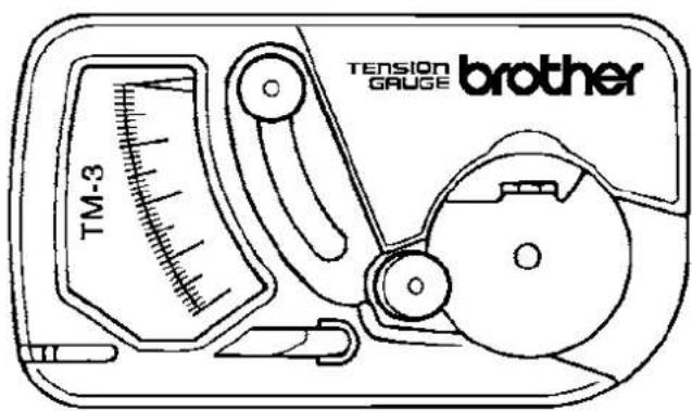
We recommend the use of the option gauge set TM-3 (S59956-001).
Chapter 3
Embroidering Procedures
After installation of machine and setting-up of the personal computer (PC), start embroidering. This chapter explains about the operation panel on the machine as well as precautions for the actual embroidering process.
Functions of Operation Panel
Operation Panel

W1368Q
Starts embroidering.
Restarts after moving the carriage to embroidering start position by using the jog switch.
Restarts embroidering after a suspension.

Cancels errors during embroidering.
Exits from the embroidering mode. Hold down this switch and press 📣ch.
Suspends embroidering.
Reset the inching mode when this switch is pressd.

Trims thread during suspension.

Checks the embroidering area.
Exits from embroidering mode. Press this switch while holding down STOP switch simultaneously to stop embroidering.
Moves the hoop automatically into the embroidering area when the embroidery position is out of the area.
When this switch is pressed while the computer has given a command to move embroidery hoop, the embroidery hoop moves designated position.

Moves the hoop to software-set position. When this switch is pressed again, the hoop returns to the previous position.
Clear inching when this switch is pressed in the inching mode.

Moves the needle bar. The needle moves by the diameter every time this switch is pressed.

natural_image
Simple geometric diagram with four directional arrows (triangle, triangle, arrow, and inverted triangle) arranged around a central circle, enclosed in a rounded square border (no text or symbols)Moves the hoop.
Step-back or forward is available during suspension. (Use ◀▷ switches only.)
Changes the speed range during embroidering (Use switches only).
Sets machine to the inching mode when is pressed while holding down STOP during suspension.
Carries out inching of the hoop when the switch is pressed in the inching mode. (☐☐☐) appears on the panel)
Turning on the power with △key pressed will display the test mode screen.
■Canceling errors
When an error message appears, it is canceled by pressing STOP switch.
Pressing other switches can stop alarm sound.
When thread breakage or wiper out error has occurred, step-back or forward switch can be used to cancel errors.
Switches at Machine Heads

■Stop switch
Stops embroidering operation.
In BE-1206B models, this switch is located between the head 2 and 3, and also between the head 5 and 6.
In BE-1204B/1204C models, this switch is located between the head 1 and 2, and also between the head 3 and 4.
■Start switch
Starts embroidering. Holding down this switch executes embroidering at a low speed.
In BE-1206B models, this switch is located between the head 2 and 3, and also between the head 5 and 6.
In BE-1204B/1204C models, this switch is located between the head 1 and 2, and also between the head 3 and 4.
■STEP BACK/FWD switch
When BACK switch is pressed, the machine steps back. When FWD switch is pressed, the machine steps forward. If you keep the switch pressed for a while, the machine will continue stepping even after you let the switch alone.
If any error occurs, it can be reset.
When the sewing is suspended during the area checking, pushing this switch can move the head to the previous or the next vertex of the outlined rectangle pattern.
In BE-1206B models, switches are located between the head 1 and 2, and also between the head 5 and 6.
In BE-1204B/1204C models, switches are located between the head 1 and 2, and also between the head 3 and 4.
Lamps and switches on the thread tension stand
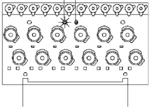
The thread tension stand has lamps and switches mounted on it.
Switches can set movements of the heads such as to drive, to suspend or mending, and those statuses can be checked by lamps.
Thread tension stand lamp Thread tension stand switch
natural_image
Top-down schematic of a multi-level device layout with circular components and a star symbol (no text or labels)W1258Q
■ Thread tension stand lamp
Shows statuses of each head of the machine.
| Lamp illumination Machine head status | |
| Off | The head is suspended |
| The head is not suspended but its mending is set to OFF. | |
| Some other head has an error. | |
| Illuminates green The head is ready to drive. | |
| Blinks green The head has an error. Blinking will change into illuminating when the error is cleared. | |
| Blinks red | The head has a thread breakage error. Blinking will change into illuminating when the error is cleared. |
■Thread tension stand switch
Sets drive/suspend of each head and ON/OFF of the mending.
Mending is a function to drive or suspend the head for the specified time period when the machine steps back during embroidering.
- Switching of drive/suspend should be done when the machine is stopped.
- Switching of the mending should be done when the machine is suspended during embroidering.
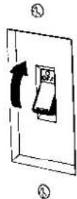
Flip the switch up to suspend the head.
Flip up the switch further to switch ON/OFF the mending.
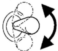
Flip the switch down to suspend the head.
W1259Q
Flowchart of Preparation for Embroidering
Run PC.

Run software ( page 3-7).

Turn on the machine power. ( page 3-7)

Register the machine name for initial start-up. ( page 3-8)
Retrieve the embroidery data by using explorer ( page 3-8).
"Chapter 4 Selecting and Transferring Embroidery Data" ( page 4-1)

Edit the retrieved embroidery data.
"Chapter 5 Editing Embroidery Data" ( page 5-1)
Click

Press

e operation panel.

Press

the operation panel.
Run the Software
- Select [Program] - [Brother Embroidery System] - [Ecsc] from the Start menu.
The software starts up.
Turn on the Machine Power
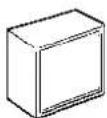
Main power switch
Emergency stop switch
Flat / Cap hoop select swich
Power switch


W1262Q W1265Q W1405Q W1266Q
- Turn on the main power switch.
- Reset the emergency stop switch.
- Change the Flat / Cap hoop select switch according to the hoop to be used.
- Press the power switch.
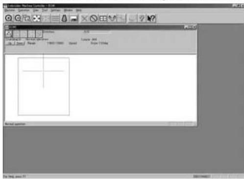
- The computer screen changes when the machine is turn on.
W1369Q
Register the Machine Name
Enter the machine name if the software is run for the first time or when a new machine is connected.
- Enter a machine name.

- Click [OK].
Retrieve the Embroidery Data
- Click

The embroidery data explorer starts up.
- Double-click the desired data or click after clicking the desired data.
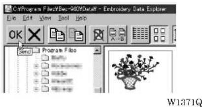
- The selected data is transferred to the machine controller.

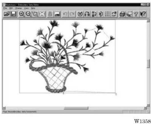
natural_image
Black-and-white line drawing of a potted plant in a basket, displayed within an image editing software interface (no text or symbols on the diagram itself)- Click

The data is transferred to the machine for preparation of embroidering.
When the embroidery hoop is displayed, the area check is conducted not with the embroidery area but with the frame shape. However, the area check of spider net frame and cap frame is conducted with the embroidery area.
Be sure to note that at the time of the area check with the frame shape, the warning message won't be displayed when all of the embroidery data is placed apart from the embroiderable area (in green) in the frame or covers up the whole embroiderable area (in green) of the frame.
Start Embroidering
- Check that the READY lamp on the machine operation panel is on.

- Press to lock the embroidering area.
- Press to start embroidering.
Chapter 4 Selecting and Transferring Embroidery Data
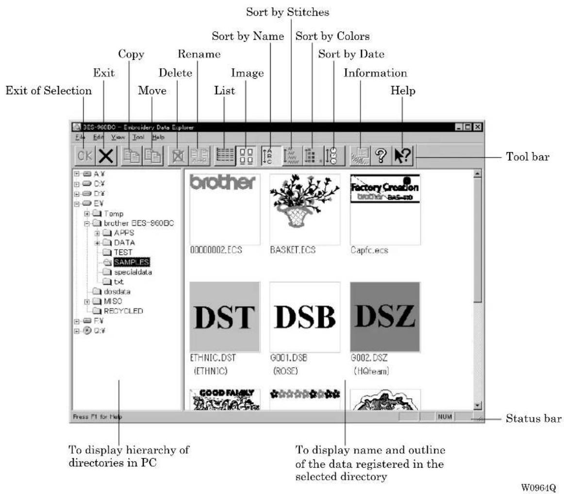
Clicking on the machine controller brings up a screen which allows selecting or transference of registered embroidery data. Moving, copying, and deleting of embroidery data can also be carried out on this screen.
Functions (Command Reference)
File menu
| New | Creates a new directory. (→ page 4-4) | |
| Exit of Selection | OK | Transfers embroidery data to the machine controller. (→ page 4-5) |
| Exit Exits from embroidery data explorer. | ||
Edit menu
| Copy | Copies the selected embroidery data. (→ page 4-7) | |
| Move Moves the selected embroidery data to a different directory.(→ page 4-8) | ||
| Delete | Deletes the selected embroidery data. (→ page 4-9) | |
| Rename | Renames the selected embroidery data. (→ page 4-12) | |
| Recreate an icon | Creates an icon of data for other models. (→ page 4-10) | |
| Select all | Selects all the data. (→ page 4-11) | |
View menu
| Tool Bar Displays the tool bar. | ||
| Status Bar Displays the status bar. | ||
| List | Displays embroidery data in the text form. (→ page 4-15) | |
| Image | Displays the image of embroidery data. (→ page 4-15) | |
| Sort by Name | Sorts embroidery data by name (in the reverse order). (→ page 4-15) | |
| Sort by Stitches | Sorts embroidery data by the number of stitches in ascending order (in descending order). (→ page 4-15) | |
| Sort by Colors Sorts embroidery data by the number of colors in ascending order (in descending order). (→ page 4-15) | ||
| Sort by Date | Sorts embroidery data by date in descending order (in ascending order). (→ page 4-15) | |
| Refresh | Displays the latest data by updating the screen. (→ page 4-15) | |
Tool menu
| Find Files | Retrieves files. (→ page 4-13) |
| DST/DSB/DSZ → ECS Conversion | Reads DOS format data. (→ page 4-16) |
| Non DOS (Barudan, ZSK...) Conversion | Reads non-DOS format data. (→ page 4-18) |
| Tape → ECS Conversion | Reads data in paper tape. (→ page 4-22) |
| ECS → DST Conversion | Converts ECS data to DST data. (→ page 4-25) |
| Setup | Defines settings of data reading. (→ page 4-24) |
Description of Screen
Creating a Directory
Creates a new directory. A directory can be created within another directory.
- Click and select a parent directory in the window on the left.
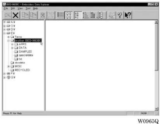
- Select [New] - [Folder] from File menu.

- Enter a new folder name.

-
Click [OK].
-
A new directory is added to the window.

Transferring data
Transfer registered embroidery data to the machine controller or Embroidery data editor.
- Double-click data, or click data and OK.
The explorer exits automatically after transferring the selected data.

W0969Q
Transferring DST and DSB data
- Double click DST or DSB data or click the data and click OK.
- The pattern image is displayed. To read the data, click [OK].

W0970Q
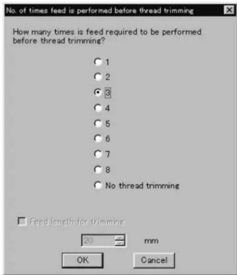
- Set the number of feeds for trim. Select the number of feeds or specify the feed length for trimming and click [OK].
The data is transferred and the explorer ends automatically.
W0971Q
Transferring data on a network
- Before starting the software, click [START] - [PROGRAM] - [EXPLORER].
- Select [Map Network Drive] from Tool menu.
- Select the desired drive and enter the path, and click [OK].
- Exit from the explorer.
If no image appears:
If no image of embroidery data appears, select "Display Detail" on "Screen" of the control panel to adjust display color.
Choose one of the following options, then restart PC.
• 256 colors
• High color (16 bits)
• Full-color (24 bits)

W0972Q
Copy
Copies embroidery data.
■Select from the menu or drag the data icon to the destination.
Select from Menu
-
Click data for selection.
-
Select [Copy] from Edit menu or click


- Select destination directory. Name copy data.

W0974Q
- Click [Save].
Drag Data
-
Click data for selection.
-
Drag data to destination directory while pressing [Ctrl] key.
The pointer turns into Release the mouse button when the directory name is inverted.

W0975Q
- Check that the copy destination directory is correct, then click [Yes].

W0976Q
Moving Data
Moves embroidery data to a different directory.
■Select from the menu or drag the data icon to the destination.
Select from Menu
-
Click data for selection.
-
Select [Move] from Edit menu or click


W0977Q
- Select the destination directory and click [Save].

W0974Q
Drag Data
-
Click data for selection.
-
Drag data to the destination directory.
The arrow pointer turns into ☐. Release the mouse button when the directory name is inverted.

W0978Q
- Check that the copy destination directory is correct, then click [Yes].

W0976Q
Deleting Data
Deletes embroidery data.
- Click data for selection.
The frame of selected data becomes red.
- Select [Delete] from Edit menu or click


- Click [Yes] to delete the selected data.
Recreate an icon
Creates an icon of data for other models.
■Icons of the data created by the following models can be recreated.
- BE-1204B-BC
- BE-1204C-BC
-
BE-1206B-BC
-
Click and select the data displayed as "Icon is not completed".
The frame of the data selected is displayed in red.
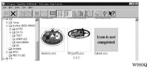
- Select [Icon is made again.] from the Edit menu.
- The pattern image is displayed.
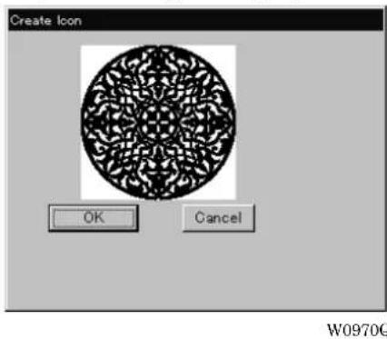
- Click [OK].
Select All
Selects all the data in the folder displayed.
■ Only copying, movement, and deletion by drag & drop are enabled when multiple patterns are selected simultaneously. Transfer to the machine controller is disabled.
- Select [Select all] from the Edit menu.
The frame of the data selected is displayed in red.
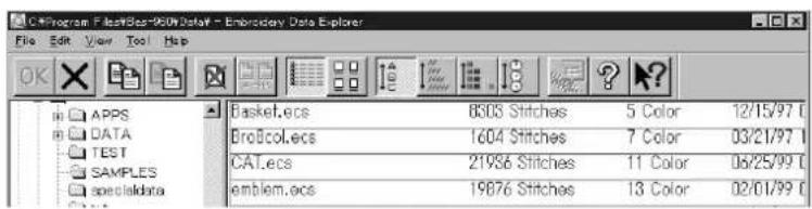
In the text display mode
W0981Q

In the image display mode
W0980Q
Renaming Data
Renames the registered embroidery data.
■ Data name consists of the name area and three characters called "extension" which indicates data type. Enter ".ECS" at the end of the data name.

W0663Q
■Upper and lower cases are not distinguished in the data name.
- Click data for selection.
The frame of selected data turns red.
- Select [Rename] from Edit menu or click

- Enter a new data name.
Enter a data name including extension.
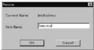
W0982Q
- Click [OK].
Finding Data
Retrieves and views embroidery data.
- Select [Find Files] from Tool menu.
- Enter the file name of embroidery data for search.
Enter the file name correctly.

W0983Q
- Click [Find].

W0984Q
If the specified embroidery data is found, the data is displayed.

W0985Q
Finding Files With Wildcard Characters
Wildcard characters can be used as a substitute of a single character or multiple characters. Characters "?" and "*" can be used as wildcard characters for search.
■Using (?)
The wildcard character "?" represents any single character. For instance, if "Basket?.ecs" is entered to the file name box, the search will find any file name including 'Basket' and a following character. Any number of wild characters can be used to replace other characters.
■Using "\*"
The wildcard character "*" represents a character or combination of characters. For instance, if "*.ecs" is entered to the file name box, the search will find all files with extension "ecs".
Adjusting Screen Display
Selects the information type to display on the screen.
■Tool bar
If it is checked, the tool bar appears.
■Status bar
If it is checked, the status bar appears.
■File display format
Choose either option.
List Displays a list of all embroidery data names and details in the directory in text format.
Image Displays a list of all embroidery data names and images in the directory.
■File sorting order
Choose one of the following options. Clicking the icon will switch between ascending order and descending order.
Sort by Name Sorts files by name.
Sort by Stitches Sorts files by the number of stitches in ascending order (in descending order).
Sort by Colors Sorts files by the number of colors in ascending order (in descending order).
Sort by Date Sorts embroidery data by date in descending order (in ascending order).
■Updating to the latest information
Displays the latest information.
- Select [Refresh] from View menu.
Reading Data in Floppy Disk
Reads data in a floppy disk and registers it as embroidery data.
■The following data formats can be registered.
| • DOS format data |
| Tajima Data with file name "xxxx.DST" |
| Barudan Data with file name "xxxx.DSB" |
| Zanks Data with file name "xxxx.DSZ" |
| • Non DOS format data |
| Barudan FDR |
| Barudan FMC |
| Zanks ZSK |
Reading DOS Format Data
- Select [DST/DSB/DSZ → ECS Conversion] from Tool menu.
- Select data to read and click [Open].
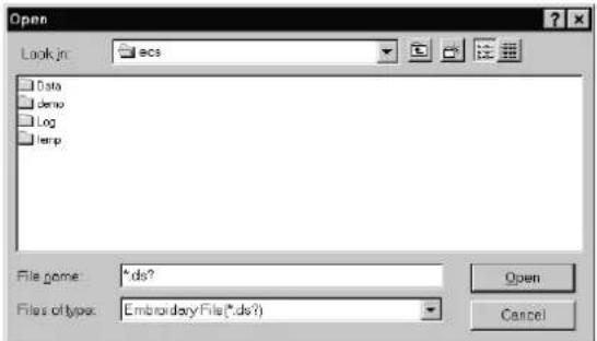
W0986Q
- The image of the selected pattern appears.
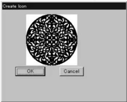
W0970Q
- Set feed counts for thread breakage. trimming and click [OK].
Select the number of feeds or specify the feed length for

W0971Q
- Select the directory to save and name the file.
Do not change extension ".ECS".

W0974Q
- Click [Save].
Converting the Non DOS format data
This function is not available with Windows NT.
Viewing Files
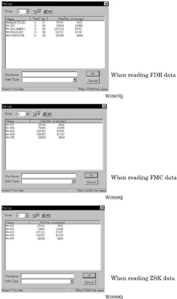
To view files of FDR, FMC and ZSK data, carry out the following steps:
■Viewing Details
Click

Names, types, Numbers, sizes, number of stitches of FDR data are displayed.
Names, sizes, number of stitches of FMC data are displayed.
Names, Numbers, sizes, number of stitches of ZSK data are displayed.
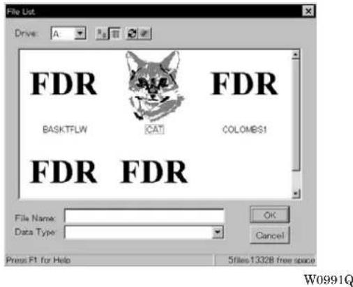
■Viewing Icon

■Preview and Refresh
The data image can be displayed before reading the data. Click the desired icon or the name for display. Click 📄 to display the data image. On the detailed display, "fdr" and "fmc" changes to image display. To cancel the preview, click 📄.
- Set the floppy disk such as Barudan which is non-DOS format at the floppy disk drive of the PC.
- Select [Non DOS (Barudan, ZSK...) Conversion] from Tool menu.
3. Select data to read and click [OK].

When "Details" is selected W0992Q

When "Icon" is selected W0993Q
- The image of the selected pattern appears. To convert the selected data into ECS data. Click [OK].

W0994Q
- Set feed counts for thread breakage. Select the number of feeds or specify the feed length for trimming and click [OK].
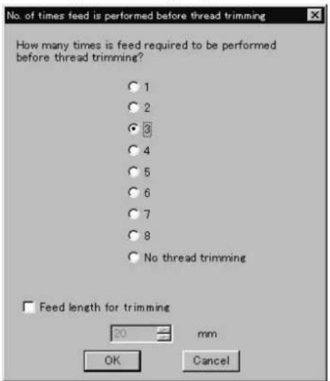
W1403Q
- Select the directory to save the file and name the file.
Do not change extension ".ECS".

W0995Q
- Click [Save].
Reading Data in Paper Tape
Saves data in paper tape as embroidery data.
■Paper taper reader is required for reading data.
■ Before saving any data, check that the paper tape reader is connected to PC correctly.
■Available interfaces are as follows:
• COM1
• COM2
■Readable data formats of paper tape are as follows:
• Tajima
- Barudan
• Zanks (ZSK)
- Turn on the power to the paper tape reader.
- Set paper tape after the LED of READ button light up.

W0414Q
- Select [Tape → ECS Conversion] from Tool menu.
- Select data format and click [OK].
The paper tape reader starts reading data.
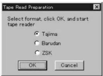
W0996Q
- The image of the selected pattern appears.

W0970Q
- Select the directory to save and name the file.
Do not change extension ".ECS".
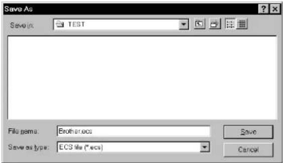
W0997Q
- Click [Save].
Settings for Data Reading
Sets up the interface and data transfer speed of the paper tape reader or external disk drive.
- Select [Setup] from Tool menu.
- Select port and speed.

W0998Q
- Click [OK].
Writing Data in DST Format
Convert the ECS data into DST data for saving.
- Click the desired ECS data to convert into DST data.
-
Select [ECS to DST conversion] from Tool menu.
-
Select the directory to save and name the file.
Do not change extension ".dst".

W0999Q
- Click [Save].
- Set feed counts for thread breakage. Select the count and click [OK].

W0971Q
Viewing Pattern Information
Detail information of embroidery data can be checked.
■The following items can be checked.
| Pattern name File name and path of embroidery data |
| File Version Version number of the file |
| No. of stitches The number of stitches in embroidery data |
| No. of colors The number of colors used in embroidery data |
| Mask Size Size of masking |
| Start of Embroidering Coordinates of embroidering start position |
| End of Embroidering Coordinates of embroidering end position |
| Last modified Date of last revision of data |
- Click data for selection.
The frame of the selected data turns red.
- Select [Design Information] from Help menu or click

- After checking, click [OK].
Chapter 5
Editing Embroidery Data
Clicking of the machine controller brings up a screen which allows editing of embroidery data. This screen allows simple processing of embroidery data and display setting of display.
Functions (Command Reference)
File menu
| Open |  | Selects embroidery data. (→ page 5-5) |
| Merge | Add other pattern to the pattern in editing. (→ page 5-28) | |
| Save |  | Saves the edited embroidery data over the current file. (→ page 5-30) |
| Save as | Saves the edited embroidery data as a separate file. (→ page 5-31) | |
 | Prints embroidery data. (→ page 5-33) | |
| Print Preview Views printing condition of embroidery data. | ||
| Print Setup Designates printer settings. | ||
| Exit Editing Exits from editing of embroidery data. | ||
Edit menu
| Undo | [YXBW] | Returns to the previous step. (→ page 5-15) |
| Redo | [AT6Z] | Repeats the step of "Undo". (→ page 5-15) |
| Rotate |  | Rotates the image. (→ page 5-16) |
| Horizontal Flip |  | Flips the image horizontally. (→ page 5-17) |
| Vertical Flip |  | Flips the image vertically. (→ page 5-17) |
| Point Symmetry | [T0TD] | Rotates the image 180 degrees about the center. (→ page 5-17) |
| Repeat |  | Repeats copying of the image. (→ page 5-17) |
| Resize | [XY5S] | Resizes the image. (→ page 5-20) |
| Delete Stitch | Delete a stitch whose length is the designated length or less. (→ page 5-20) | |
| Insert or delete code | Insert or delete the code for trim, pause and color change. (→ page 5-21) | |
| Insert lock stitch | Insert a lock stitch before and after thread trimming. (→ page 5-22) |
Change menu
| Start | Changes the start position of embroidery data. (→ page 5-23) |
| End | Changes the end position of embroidery data. (→ page 5-24) |
| Mask | Changes the mask of embroidery data. (→ page 5-25) |
| Group | Group the patterns created in "Repeat" into one. (→ page 5-26) |
View menu
| Centering | Centers embroidery data. (→ page 5-6) |
| Zoom | Zooms in or out. (→ page 5-6) |
| Needle Penetration | Displays the needle penetration positions. (→ page 5-8) |
| Embroidering Start/End | Displays the start/end positions of embroidering. (→ page 5-8) |
| Trim and pause | Displays the code insertion position for trim and pause. (→ page 5-8) |
| Microstitch Displays the position of the stitch whose length is the designated length or less. (→ page 5-9) | ||
| Needle bar and speed range |  | Displays the setting screen for needle bar and speed range. (→ page 5-9) |
| Thread color | [SDYD] | Displays the pattern in thread color. (→ page 5-13) |
| Tool Bar | Shows/hides the tool bar. (→ page 5-14) | |
| Status Bar | Shows/hides the status bar. (→ page 5-14) | |
Description of Screen
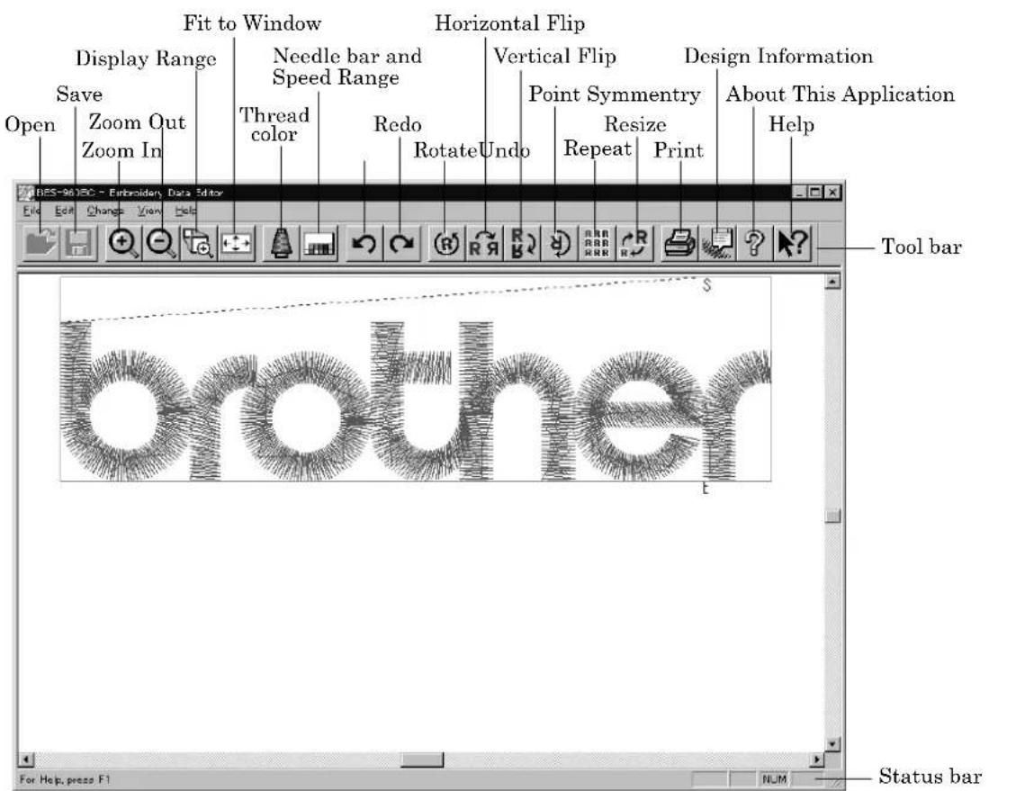
W1000Q
Opening Embroidery Data
This function is available with embroidery data editor.
- Select [Open] from File menu or click

- Double-click the data or click the data and


W1001Q
Setting Display
Sets the condition of the display screen. Items with check marks to the left are selected.
Centering
Brings the image to the center of the screen.

Before selecting After selecting
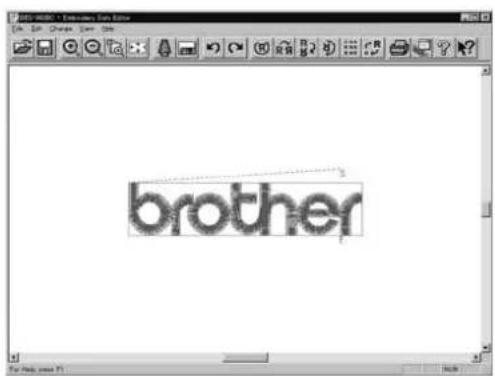
W1002Q W1003Q
- Select [Centering] from View menu.
Zoom
Zooms in/out the pattern.
■The following four types of zooming are available.
Zoom In Enlarges the image to 125%.
Zoom Out Reduces the image to 80%.
Range Magnifies the range defined by the mouse to the full window size.
Full Window Displays the whole image to the size of the window.
Zoom In
- Select [Zoom] - [Zoom In] from View menu or click

Repeats zooming of the image by the number of clicks.

Before selecting After selecting

W1002Q W1004Q
Zoom Out
- Select [Zoom] - [Zoom Out] from View menu or click

Repeats zooming of the image by the number of clicks.

Before selecting After selecting
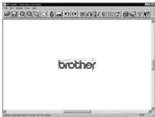
W1004Q W1005Q
Range
- Select [Zoom] - [Range] from View menu or click

- Drag and define the range to zoom in with the mouse.

Before selecting After selecting
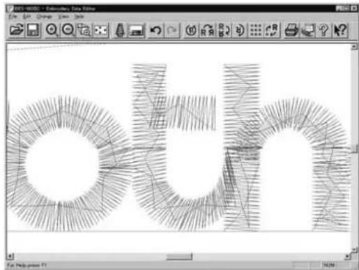
natural_image
Abstract geometric pattern with interlocking circular and curved lines forming a 3D shape (no text or symbols)W1005Q W1006Q
Fit to window
- Select [Zoom] - [Fit to window] from View menu or click


Before selecting After selecting

W1005Q W1007Q
Needle Penetration
Chooses whether or not the needle penetration positions are displayed.
- Select [Needle Penetration] from View menu.
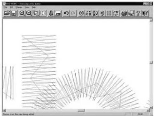
natural_image
Pure geometric line drawing with intersecting lines and arcs, no text or symbols presentBefore selecting After selecting
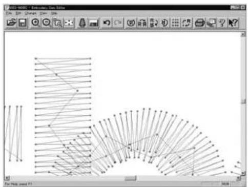
flowchart
graph TD
    A["Start"] --> B{Transformation}
    B --> C["Step 1"]
    B --> D["Step 2"]
    B --> E["Step 3"]
    B --> F["Step 4"]
    B --> G["Step 5"]
    C --> H["Final Output"]
    D --> H
    E --> H
    F --> H
    G --> H
W1008Q W1009Q
Embroidering Start/End
Displays start and end points as "S" and "E" on the screen respectively. If points "S" and "E" are identical, "E" has priority over "S".
- Select [Embroidering Start/End] from View menu.
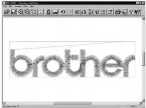
Before selecting After selecting

W1010Q W1011Q
Trim and pause
Displays the position of the trim code and the pause code. Trim is displayed by X and pause is displayed by .
- Select [Trim and pause] from the View menu.
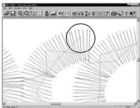
natural_image
Abstract line drawing with intersecting lines and a circled region, displayed in an image editing interface (no text or symbols on the diagram itself)
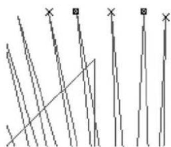
natural_image
Abstract geometric pattern with diagonal lines and a diagonal line intersecting at the intersection (no text or symbols)W1012Q W1013Q
Microstitch
Displays the position of the stitch whose length is less than the designated length with Length can be designated from 0.0 to 1.0 mm in units of 0.1 mm.
-
Select [Microstitch] from the View menu.
-
Designate the length of the stitch to be viewed. Select [View] and designate the length of the microstitch.

W1014Q
- Click [OK].

natural_image
Sketch-style drawing of a person in profile view, showing abstract shapes and shading (no text or symbols)Before selecting After selecting W1015Q W1016Q

Needle Bar and Speed Range
Displays status of the needle bar and speed range.
- Select the [Needle bar and speed range] from the View menu or click

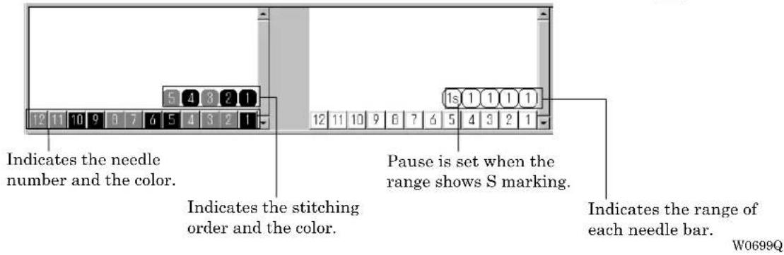
Change of display color
■ When the color of the embroidering sequence is changed, the color displayed on the screen is changed. When ending embroidering or reading other data, the confirmation screen for saving the setting appears.
■A display color can be selected from among the following four items.
| Basic color which can be selected screen on the "Color selection" | Refer to steps 1 and 2. |
| Color sample supplied by a manufacturer Refer to steps 1 and 3. | |
| Color sample created by a user Refer to steps 1 and 3. | |
| Adjustment of an intermediate color from the color sample supplied by a manufacturer or naming and registration of a newly created color | Refer to steps 1 to 7. |
■ The following screen is displayed when colors to be displayed are set to 256 in [Display Properties] and the color sample supplied by a manufacturer cannot be selected or an intermediate color cannot be created.
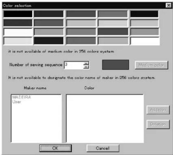
W1017Q
- Double click the desired embroidering sequence to change the color.

W0699Q
- Select a new color on the [Color selection] screen.
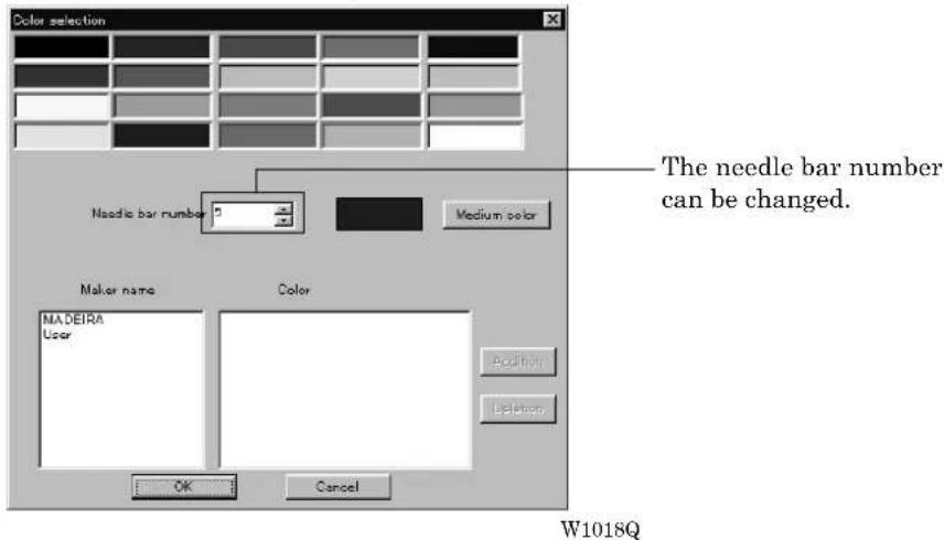
- When selecting a color from a color sample, click maker name or [User] and double click [Color].

- When finely adjusting the selected color, click [Medium color]. Click [User] to crate a new color, then click [Addition].

5. Select an arbitrary color from basic colors.
Click [Define Custom Colors] to create a medium color.
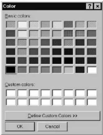
W1021Q
6. Select a color by clicking on the color chart or by inputting a value, and click [OK].

W1022Q
7. Input the name of the color and click [OK] when [User] is selected in step 4.

W1023Q
Changing needle bar allocation
- Drag the embroidering sequence on the needle bar number.

Setting the range
-
Double click the desired needle bar range to change.
-
Click the desired range.

- Click [OK].
Thread Color
The embroidery data is displayed in thread color.
■ This functions is available only when the embroidery data edit is started from the machine controller.
- Select [Thread color] from the View menu or click

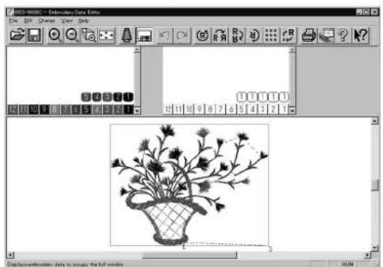
Before selecting After selecting
W1026Q W1027Q
Tool bar
Shows/hides the tool bar. The tool bar contains icons with the same functions as the menu.
1. Select [Tool Bar] from View menu.

Before selecting After selecting

W1028Q W1029Q
Status Bar
Shows/hides the tool status. The status bar provides information on the current status and advice for operation.
1. Select [Status Bar] from View menu.
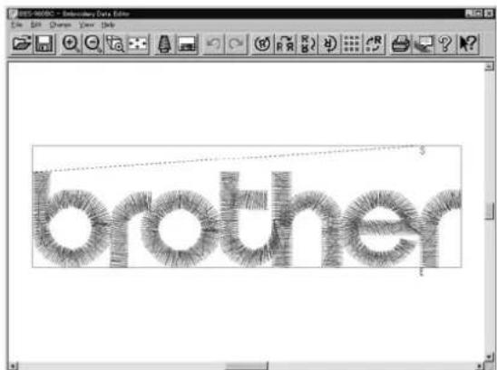
Before selecting After selecting

W1030Q W1029Q
Back to Previous Status
Undo
Makes the edit or change invalid. The screen returns to the state before the change.
■The screen can return to 3 steps maximum.
- Select [Undo] from the Edit menu or click

Redo
Repeats the canceled step of "Undo".
■The screen can return to 3 steps maximum.
- Select [Redo] from the Edit menu or click

Editing
Rotate

W0558Q
■Available range of rotation is -359 to 359 degrees.
■ When the patterns to be repeated are grouped, the whole pattern rotates. When they are not grouped, each pattern rotates in each hoop.

natural_image
Illustration of three identical plant rows with stems and leaves, connected by dashed lines (no text or symbols)
When the patterns are grouped When the patterns are not grouped W0713Q W0714Q
- Select [Rotate] from View menu or click

- Select angle.
If [Free] is selected, specify the angle.

The value can be directly entered.
W1032Q
- Click [OK].
Horizontal Flip
Flips the image horizontally.

W0450Q W0459Q
- Select [Horizontal Flip] from Edit menu or click .
Vertical Flip
Flips the image vertically.

W0450Q W0460Q
- Select [Vertical Flip] from Edit menu or click .
Point Symmetry
Flips the image 180 degrees to the center position of the image.

W0450Q W608Q
- Select [Point Symmetry] from Edit menu or click .
Repeat
Repeats copying of the image by the specified number.

W0450Q W0464Q
■ The number for repetition is 1 to 100 for both vertical (Row) and horizontal (Column) directions.
■ The unit for repetition can be set in inches. To use the inch unit, set the length to [inch] on the [Configuration] of Tool menu of the machine controller. (→ page 6-24)
■The pattern connection can be set in "Direction" as follows:
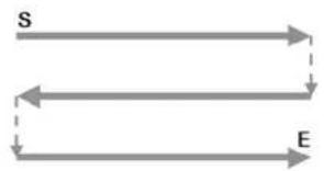
flowchart
graph TD
    S --> E
    E --> S
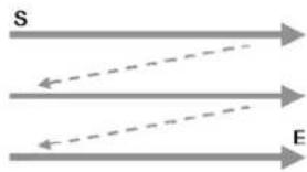
From top left, alternating directions From top left, left to right direction
W0716Q W0717Q

flowchart
graph TD
    A["S"] --> B["E"]

From bottom left, alternating directions From bottom left, left to right direction
W0718Q W0719Q
-
Select [Repeat] from Edit menu or click .
-
Specify the number, interval and direction of repetition.

W1033Q
- Click [OK].
Margin setting with [Auto setting] selected
The number is set automatically so as the number of repetitions to be the maximum within the sewing area.
■ When [Spacing], [Direction], and [Datum] are pre-selected before [Auto setting] is selected, the setting is performed according to pre-passings.
■ [Margin] can be set after [Auto setting] is selected and the margin size you can set is 5 \~ 100mm (0.2 \~ 4.00' in inch) around the sewing area.
Margin setting is performed as follows:
- Select [Auto setting] and click [Margin].
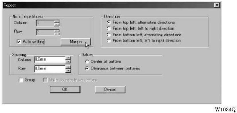
- Set the vertical and horizontal margin for sewing area.

- Click [OK].
- Click [OK].
Resize
Resizes the image.

W0450Q W1395Q
■The available range of resizing is 50 to 200% in both the X and Y directions.
■Resizing changes the thread density along with the percentage.
- Select [Resize] from Edit menu or click

- Specify the percentage of resizing.
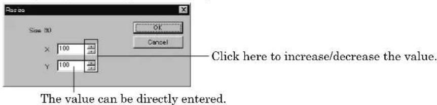
W1036Q
- Click [OK].
Delete Stitch
Delete a stitch whose length is less than the designated length. Length can be designated from 0.0 to 1.0 mm in units of 0.1 mm.
-
Select [Stitch deletion] from Edit menu.
-
Designate the length of the stitch to be deleted.

W1037Q
-
Click [OK].
-
Deleted result is displayed. Click [OK].
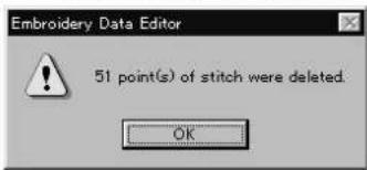
W1038Q
Insert or Delete Code
Codes of trim, pause and color change can be inserted or deleted by moving the needle to the desired position.
1. Select [Insert or delete code] from the Edit menu.
Needle movement tool bar is displayed.

2. Select the movement method of needle position.
Click either of the following buttons:
| 1 step | 1 | Moves the needle position by 1 step each. |
| 10 step Moves the needle position by 10 step each. | ||
| 100 step Moves the needle position by 100 step each. | ||
| Next (previous) color change point | ^ | Moves the needle position to the next (previous) color change point. |
| Next (previous) feed point Moves the needle position to the next (previous) feed point. | ||
| Next (previous) trim code Moves the needle position to the next (previous) trim code. | ||
| Next (previous) pause code Moves the needle position to the next (previous) pause code. | ||
3. Move the needle position to the desired position.
Click either of the following buttons:
| Consecutive step backward specified | ◀◀ | The needle position returns consecutively until the "Stop" button is pressed. |
| Step backward specified The needle position returns for the specified length. | ||
| Stop The needle position stops movement. | ||
| Step forward specified | ▶▶ | The needle position moves forward for the specified length. |
| Consecutive step forward specified | ▶▶ | The needle position moves forward consecutively until the "Stop" button is pressed. |
| Number | Move the needle directly to the indicated position. | |
4. Insert or delete the code.
Click either of the following buttons:
| Insert (delete) trim code | Insert (or delete) the trim code at the current needle position. | |
| Insert (delete) pause code | Insert (or delete) the pause code at the current needle position. | |
| Insert (delete) change color code | Insert (or delete) the change color code at the current needle position. |
- To end code insertion or deletion, click OK . Modified setting is saved. To cancel the modification of setting, click ✗.
Insert Lock Stitch
Find the pattern of [Stitch] - [Trim] for [Before Trimming] and find the pattern of [Trim] - [Feed] - [Stitch] - [Stitch] for [After Trimming], then insert a lock stitch.
■ Insertion method of lock stitch depends on the length of the second stitch as follows:
| Stitch length Method of lock stitch |
| 1.2 mm or more Insert 3 stitches of 0.3 mm stitch. |
| From 0.9 mm to less than 1.2 mm Insert 2 stitches of 0.3 mm stitch. |
| From 0.6 mm to less than 0.9 mm Insert 1 stitch of 0.3 mm stitch. |
| Less than 0.6 mm Do not insert the lock stitch. |
■ The inserted lock stitch cannot be deleted. However, use [Undo] in the Edit menu to return to the status before inserting the lock stitch just after the lock stitch is inserted.
-
Select [Insert lock stitch] from the Edit menu.
-
Designate the position to insert the lock stitch and click [OK].
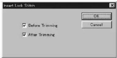
W1040Q
- If the lock stitch can be inserted, click [Yes].
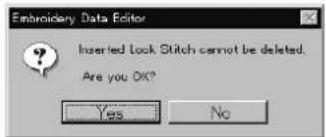
W1041Q
Changing Data
Changing Start
Changes the start position of embroidering.
Options Functions
| Center, upper left corner, middle left corner, lower left corner, middle top edge, middle bottom edge, upper right corner, middle right corner, or lower right corner of the mask | Starts embroidering at the specified position. |
| Specify using mouse Starts embroidering at the position clicked with the mouse. | |
Cancel Cancels the specified position.
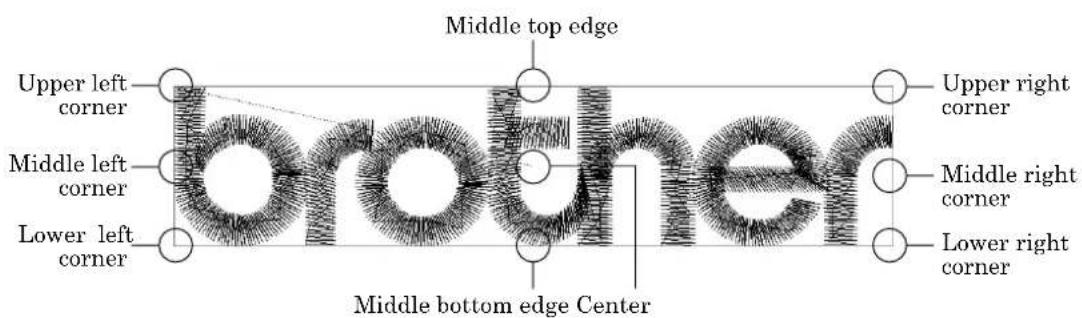
W0729Q
1. Select [Start] from Change menu.
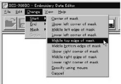
Click the start position if [Specify using mouse] is selected.
W1042Q
Changing End
Changes the end position of embroidering.
Options Functions
Center, upper left corner, middle left corner, lower Ends embroidering at the specified position.
left corner, middle top edge, middle bottom edge, upper right corner, middle right corner, or lower right corner of mask.
Specify using mouse
Ends embroidering at the position clicked with the mouse.
End at start position Ends embroidering at the end position.
Cancel Cancels the specified position.
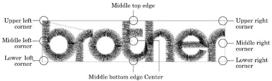
W0729Q
1. Select [End] from Change menu.
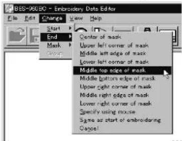
Click an end position if [Specify using mouse] is selected.
W1043Q
Mask
Changes the mask that represents the periphery of embroidery data. Since the automatic mask is a rectangle, the pattern within the hoop may be displayed as an error. In this case, set masking in manual mode.
■Mask is displayed in a khaki line.
■There are two types of mask setting as follows:
Automatic The system measures the image size to create a mask automatically.
Manual After selecting this mode, specify the mask area using the mouse.
- Select [Mask] from Change menu. Select automatic or manual mode.
If [Automatic] is selected, a mask is created automatically.
If [Manual] is selected, drag the area with the mouse to specify the mask.

W1044Q
Group
All patterns created in repetition are grouped as a single pattern.
■The difference between the grouped pattern and the non-grouped pattern is as follows:

When the patterns are grouped
• Each pattern is displayed in each mask.
• The whole grouped pattern rotates. (→ page 5-16)
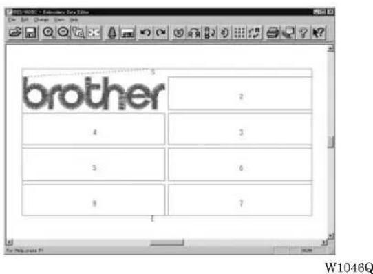
When the patterns are not grouped
- The pattern is displayed only in the original copy source. embroidering sequence.
Figures in other masks represent the
• Each pattern in the mask rotates individually. (→ page 5-16)
Setting Group for Repetition
-
Select [Repeat] in the Edit menu or click .
-
Click the checkbox of [Group] to put a check mark.
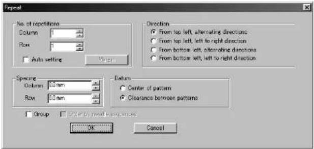
W1033Q
Selecting from Menu
- Select [Group] from Change menu.
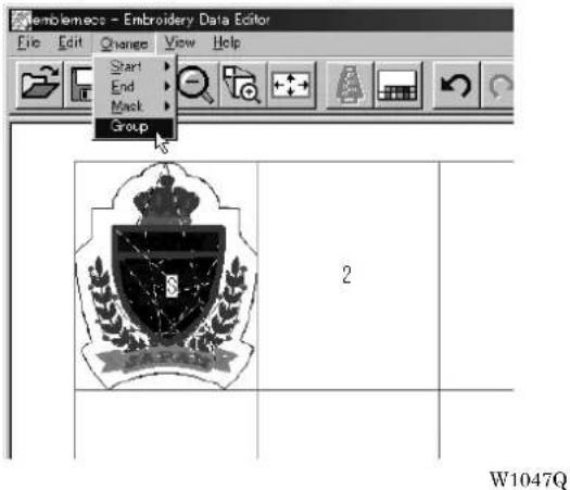
Merge
Merge other patterns to the pattern in editing.
■ If the pattern to be merged is repetition data, it is automatically grouped and merged.
■ If the pattern to be merged is grouped repetition data, it is merged at the specified position.
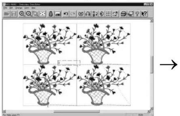
natural_image
Four identical black-and-white floral illustrations in a grid, displayed within a software interface (no text or symbols on the images themselves)
W1048Q W1049Q
■ If the pattern to be merged is non-grouped repetition data, it is merged to each pattern. If the pattern does not fit the mask, the mask is automatically adjusted.


W1050Q W1051Q
- Select [Merge] from the File menu.
- Select the pattern to be merged.

W1052Q
- The pattern mask is displayed in a broken line. Move the mask to the desired position for merging. Click the mouse.
Move the mouse while pressing the shift key. The mask moves horizontally and vertically.

natural_image
Black-and-white line drawing of a potted plant with slender branches and a mesh basket, displayed within an image editing interface (no text or symbols on the plant itself)W1053Q
- If the position is acceptable, click [Yes].
When [No] is clicked, repeat the steps from 3.
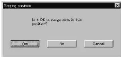
W1054Q
- The pattern is merged.
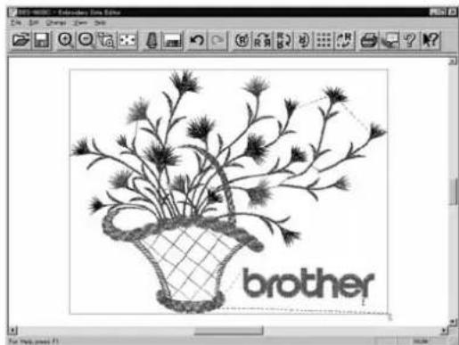
natural_image
Black-and-white line drawing of a potted plant with fronds and leaves, labeled 'brother' at the bottom (no other text or symbols)W1055Q
Saving Data
Saves the edited data. The edited data can be saved over the current file or renamed as a separate file.
Save
Saves the edited data over the current file. The original data is deleted.
- Select [Save] from File menu or click

- If the edited data is larger than the mask, choose whether to carry out automatic masking or not.

W1056Q
- If color etc. has been is changed, the pattern image appears.

Save As...
Renames and saves the edited data as a new file.
- Select [Save as...] from File menu.
- Select the directory to save the new file. Enter a new file name.

W1058Q
- Click [Save].
- If the edited data is larger than the mask, choose whether to carry out automatic masking or not.

W1059Q
- If color etc. has been is changed, the pattern image appears.

W1057Q
Viewing Pattern Information
Detail information of embroidery data can be checked.
■The following items can be checked.
| No. of stitches The number of stitches in embroidery data |
| No. of colors The number of colors used in embroidery data |
| Mask Size Size of masking |
| Start of Embroidering Coordinates of embroidering start position |
| End of Embroidering Coordinates of embroidering end position |
- Select [Design Information] from Help menu or click

- After checking, click [OK].
Printing Data
Prints data in editing.
- Select [Print] from File menu or click

Specify the number of copies and other conditions. Click [OK].
Chapter 6 Embroidering
The PC controls the machine operation as well as settings of the machine. Note that the menu which appears on the screen depends on whether the power to the machine is turned on or off.
Functions (Command Reference)
When the Power to the Machine is Off
File menu
| Save | The machine data is overwritten for saving. (→ page 6-58) |
| Save As | The machine data is saved as a different name. (→ page 6-58) |
| Exit Exits the machine controller. | |
View menu
| Tool Bar | Displays the tool bar. (→ page 6-6) |
| Status bar | Displays the status bar. (→ page 6-7) |
Tool menu
| Edit Embroidery Data Runs the embroidery data editor. | |
| Embroidery Data Explorer Runs the embroidery data explorer. | |
| Production Report Runs the production report. | |
| Upgrade Interface Board | (→ page 6-7) |
| Reset Interface Board | (→ page 6-7) |
Configuration menu
| Communication Port Sets the communication port between the PC and machine. (→ page 6-7) | |
| Language | Changes display language. (→ page 6-8) |
When the Power to the Machine is On
Machine menu
| Minimize Window Size | Minimizes the size of display screen on the machine. (→ page 6-21) |
| Rename Machine | Renames the machine. (→ page 6-19) |
| Machine Information | Displays machine information. (→ page 6-20) |
| Exit Exits from the machine controller. | |
Operation menu
| Start Embroidering | Starts embroidering. (→ page 6-49) |
| Stop Machine | Suspends embroidering. (→ page 6-50) |
| Cancel Embroidering | Cancels embroidering. (→ page 6-50) |
| Home Position | Moves the home position. (→ page 6-51) |
| Step F/B | Carries out step-forward or step-back. (→ page 6-52) |
| Move Embroidery Position | Moves embroidering position. (→ page 6-56) |
| Centering Pattern | Moves pattern to the center. (→ page 6-57) |
| Test | Tests the machine. (→ page 6-59) |
View menu
| Tool Bar | Displays the tool bar. (→ page 6-9) |
| Status Bar | Displays the status bar. (→ page 6-9) |
| Zoom In | |
| Zoom Out | |
| Zoom In Specified Range | |
| Fit to Window | |
| Whole Pattern | |
| Grid | Displays 1 x 1 cm square grids on the background. (→ page 6-11) |
| Hoop | Displays the outline of embroidery hoop. (→ page 6-11) |
| Hoop position fine adjustment | Adjusts the view position of the embroidery hoop. (→ page 6-11) |
| Needle Penetration | |
| Thread Color Adjusts the color of the embroidery data to the thread spool. (→ page 6-13) | |
| Needle Bar and Speed Range | Displays needle bar and speed range. (→ page 6-13) |
| Grid Setting | Sets the color and the pitch of grid. (→ page 6-18) |
| Background color | Changes the background color of the data. (→ page 6-18) |
Tool menu
| Language | Changes display language. (→ page 6-8) |
| Edit Allows editing of embroidery data. | |
| Embroidery Data Explorer Allows selection of embroidery data. | |
| Production Report Creates production report. | |
| Run Embroidery Data Editor independently | Runs the embroidery data editor. (→ page 6-60) |
| Run Embroidery Data Explorer independently | Runs the embroidery data explorer. (→ page 6-60) |
| Copy to Another Machine | Copies embroidery data to other machines. (→ page 6-23) |
| Configuration | Sets configuration for embroidering. (→ page 6-24) |
| Version Upgrades | Upgrades the version of the machine parts. (→ page 6-24) |
Settings menu
| Needle | Uses the same needle bar for all embroidering. (→ page 6-25) |
| Same Speed Range | Sets the head. (→ page 6-26) |
| Pause Sets whether to stop the needle bars temporarily when changing all the needle bars. (→ page 6-26) | |
| Speed Range | Defines the speed range. (→ page 6-27) |
| Head Operation Suspend Cancels the head operation which is not halted on the machine side. (→ page 6-27) | |
| Hoop Feed Position | Sets the hoop feed position. (→ page 6-28) |
| Embroidery Area | Sets the area for embroidering. (→ page 6-29) |
| Embroidery Hoop | Sets the type of embroidery hoop. (→ page 6-29) |
| Thread Trimming | Sets the inching and thread removal amount. (→ page 6-31) |
| Thread Breakage Sensor | Sets operation of thread breakage sensor. (→ page 6-32) |
| Automatic Step Back | Sets automatic step back count for thread breakage. (→ page 6-33) |
| Automatic Hoop Feed Feeds hoop to the hoop feed position automatically after embroidering. (→ page 6-33) | |
| End of embroidery | Sets if the machine returns to the start point after end of embroidery. (→ page 6-34) |
| Mending | Sets details of mending. (→ page 6-35) |
| Adjust | Sets the adjusting value. (→ page 6-36) |
| Driving shaft | Set the startup speed of the main shaft. (→ page 6-37) |
| Activate escape with pause Sets whether to feed the hoop during temporary stop of the needle bars to change colors. (→ page 6-37) | |
| Short stitch speed reduction | Reduces speed when stitching in a designated small pitch. (→ page 6-38) |
| Thin / Thick material | Adjusts the timing of needle drop and hoop movement. (→ page 6-39) |
| Area trace Select the outside shape of area tracing before starting sewing. (→ page 6-40) | |
| Trace with needle No.1 | Perform the area tracing using the needle bar No. 1. (→ page 6-40) |
| Default Settings Resets changes of the machine setting to the default at the factory shipment. (→ page 6-41) | |
| Show Setting | Shows the contents of settings. (→ page 6-42) |
| Load Setting | Loads the setting details. (→ page 6-44) |
| Save Setting | Saves the changed setting. (→ page 6-45) |
| Load Hoop | Selects the hoop type. (→ page 6-46) |
| Window menu | |
| Cascade | Cascades windows. (→ page 6-20) |
| Tile | Tiles windows. (→ page 6-20) |
| Arrange Icons | Align icons. (→ page 6-22) |
Description of Screen

Settings before Turning On the Machine
Describes settings available before the machine is turned on.
■The following items can be set.
- Displaying the tool bar
- Displaying the status bar
- Upgrading the version of interface board (*)
- Resetting the interface board (*)
- Communication port
- Language
(*) Dealer engineers carries out version upgrading and resetting of the interface board.
Displaying the Tool Bar
Shows/hides the tool bar. The tool bar contains icons with the same functions as the menu.
■There are two kinds of tool bars as follows:
Main Main menu items are displayed on this tool bar.
Step Back This tool bar appears during step-back/forward.
- Select [Tool Bar] from View menu and put the check mark.
Click here again to remove the check mark. Then the tool bar disappears.

W1061Q
Displaying the Status Bar
Shows/hides the status bar. The status bar provides information on the current status and advice for operation.
- Select [Status Bar] from View menu and put the check mark.
Click here again to remove the check mark. Then the status bar disappears.

Upgrading the Version of Interface Board
Upgrades the version of interface board program connected to PC. This function is protected by a password. A dealer engineer will use this function if required.
Reset Interface Board
Resets the CPU on the interface board connected to PC to give the same effect as restart. This function is protected by a password. A dealer engineer will use this function if required.
Communication Port
Sets communication port between PC and machine.
-
Select [Communication Port] from Configuration menu.
-
Select communication port for use.
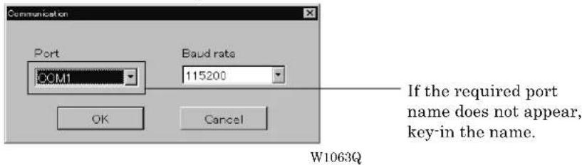
- Click [OK].
Language
Changes display language.
■The following three languages are displayed as "Available Languages".
English Displays English.
Languages system uses Displays the system language of PC.
Each respective language Displays the local language.
-
Select [Language] from Configuration menu (Tool menu when the power to machine is on).
-
Select display language among "Available Languages".
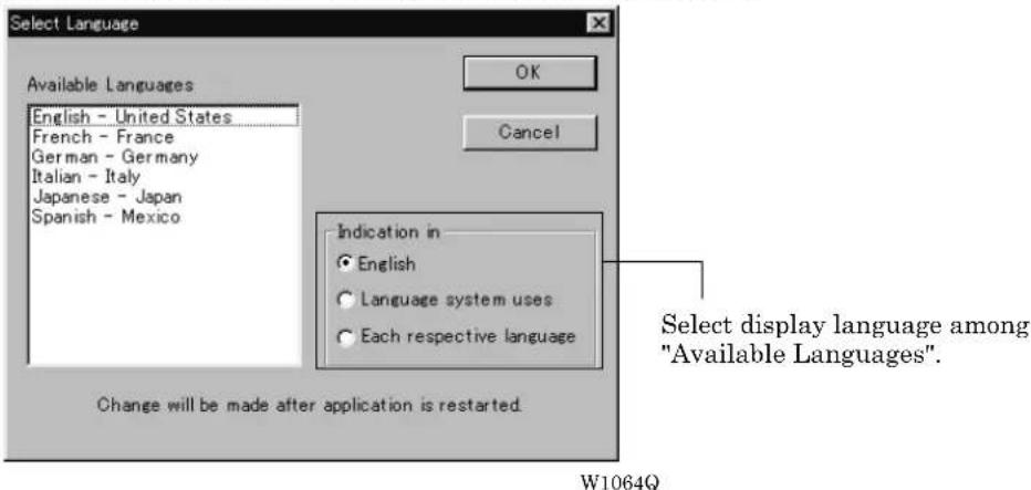
When "Each respective language" is selected, the list for "Available Languages" may not be displayed properly.
-
Click [OK].
-
Exit and rerun the software.
Settings after Turning Power On
Describes settings available after turning power on to the machine.
Tool Bar
Shows/hides the tool bar. The tool bar contains icons with the same functions as the menu.
Refer to page 6-6.
Status Bar
Shows/hides the status bar. The status bar provides information on the current status and advice for operation.
Refer to page 6-7.
Zoom In
Enlarges the image to 125%.
- Select [Zoom In] from Display menu or click

Repeats zooming of the image by the number of clicks.

natural_image
Black-and-white illustration of a circular mandala design on a white background, displayed within a software interface (no text or symbols on the drawing itself)Before selecting After selecting W1065Q W1066Q

natural_image
Black-and-white image of a circular mandala design on a white background, displayed within a software interface (no text or symbols on the artwork itself)Zoom Out
Reduces the image to 80%.
- Select [Zoom Out] from Display menu or click

Repeats zooming of the image by the number of clicks.

natural_image
Black-and-white image of a circular decorative pattern on a white background, displayed within a software interface (no text or symbols on the pattern itself)Before selecting After selecting W1065Q W1067Q

natural_image
Pure geometric diagram of a circular pattern inside a square frame, no text or symbols presentZoom In Specified Range
Enlarges the range specified with the mouse to the full window size.
- Select [Zoom In Specified Range] from Display menu or click

The arrow pointer turns into ⊕
- Drag and specify the range to zoom in with the mouse.

natural_image
Decorative circular pattern design in a graphic editing interface (no text or symbols on the pattern itself)Before selecting After selecting W1065Q W1068Q

natural_image
Abstract black-and-white line drawing of a leaf-like shape with diagonal hatching, no text or symbols presentFit to Window
Displays the whole embroidery area.
- Select [Fit to Window] from View menu or click

Before selecting After selecting W1069Q W1065Q

natural_image
Black-and-white illustration of a circular decorative pattern inside a software interface (no text or symbols on the pattern itself)Whole Pattern
Displays the whole pattern.
- Select [Whole Pattern] from View menu or click

natural_image
Circular decorative pattern design within a software interface (no text or symbols on the pattern itself)Before selecting After selecting W1065Q W1070Q

natural_image
Symmetrical black-and-white circular decorative pattern on a white background, displayed within a software interface window (no text or symbols on the pattern itself)Grid
Displays 1 × 1 cm square grids on the background.
- Select [Grid] from View menu and put the check mark.

Before selecting After selecting W1071Q W1072Q
Hoop
Displays the outline of embroidery hoop. The type of embroidery hoop can be changed in [Load Hoop] of Settings menu.
■Embroidering is allowed within the green guide in the hoop.
- Select [Hoop] from the View menu and put a check mark.
If the hoop is not displayed, carry out the step to read the hoop. For details, refer to [Load Hoop] ( page 6-46).
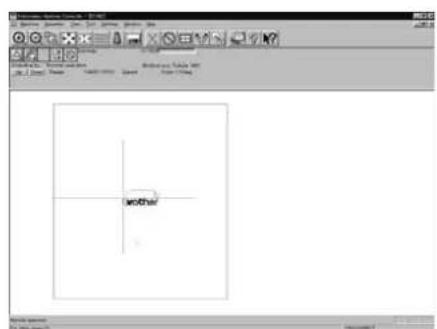
Before selecting After selecting W1073Q W1074Q

Hoop position fine adjustment
Adjusts the view position of embroidery hoop.
■The position can be adjusted in the range of ±20 mm in both the X and Y directions.
- Select [Hoop position] from the View menu.
The hoop view position is stored in the hoop data. If you reinstall the program, the hoop view position is initialized because it is overwritten.
- Designate the adjusting position and click [OK]. The hoop is displayed in a displaced position.
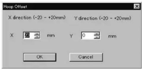
W1075Q

Before selecting After selecting W1076Q W1077Q

natural_image
Technical drawing of a square frame component with rounded corners and side handles (no text or symbols)Needle Penetration
Chooses whether or not the needle penetration positions are displayed. Clicking ☐ also provides the same function.
- Select [Needle Penetration] from View menu and put the check mark.

Before selecting After selecting W1078Q W1079Q
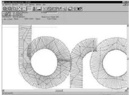
natural_image
Technical drawing of a 3D mechanical part with circular features and radial cutouts, displayed within a software interface (no readable text or symbols)Thread Color
Displays the pattern using colors currently set to the needle bar. Clicking 📁 also provides the same function.
- Select [Thread Color] from View menu and put the check mark.
Display color of the image changes.

Before selecting After selecting W1071Q W1080Q

Needle Bar and Speed Range
Displays the needle bar and speed range.
- Select [Needle Bar and Speed Range] from View menu and put the check mark or click

![Controller - [BOMO] View Tool Settings Window • Tool Bar • Status Bar Zoom In Zoom Out Zoom In Specified Range Edit to window Whole Pattern Grid Hoop Hoop Position Needle Penetration Thread Color Needle Bar and Speed Range Grid Setting 10% Back ground Color](/content/2026/05/1004755/images/34391d1033b6362e29dcaaa5a480adf699ef55cc155c5f827c2e575444293fbd.jpg)
W1081Q
Setting Needle Bar
Needle bar allocation and display color can be changed on this screen.

W1082Q
Changing display colors
■The color of needle bar changes to the actual color.
■ Changing the thread spool also changes the display color. A confirmation screen to save appears before exiting from embroidering or retrieving other data.
■A display color can be selected from among the following four items.
| Basic color which can be selected screen on the "Color selection" | Refer to steps 1 and 2. |
| Color sample supplied by a manufacturer Refer to steps 1 and 3. | |
| Color sample created by a user Refer to steps 1 and 3. | |
| Adjustment of an intermediate color from the color sample supplied by a manufacturer or naming and registration of a newly created color | Refer to steps 1 to 7. |
■ The following screen is displayed when colors to be displayed are set to 256 in [Display properties] and the color sample supplied by a manufacturer cannot be selected or an intermediate color cannot be created.

W1017Q
- Double-click the thread spool or needle bar number.

W1082Q
- Select a new color on the [Color selection] screen.
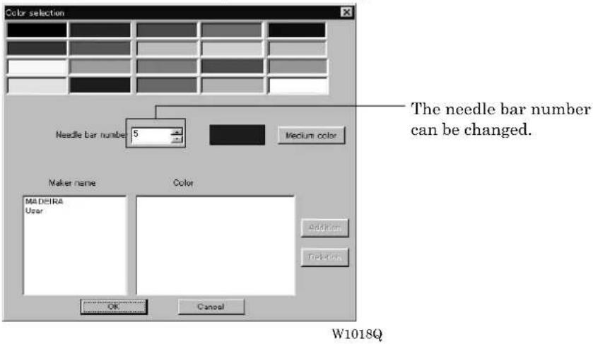
- When selecting a color from a color sample, click maker name or [User] and double click [Color].

- When finely adjusting the selected color, click [Medium color]. Click [User] to crate a new color, then click [Addition].

- Select an arbitrary color from basic colors.
Click [Define Custom Colors] to create a medium color.

W1021Q
- Click the color chart or enter values to create a new color, and click [OK].

W1022Q
- Input the name of the color and click [OK] when [User] is selected in step 4.
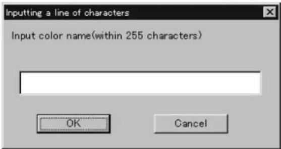
W1023Q
Changing needle bar allocation
- Drag a thread spool to the desired needle bar number.

This thread spool has been dragged
W1084Q
Setting Ranges
There are two methods for setting ranges.

Changing all ranges
- Click [Up] to increase range. Click [Down] to reduce range.
One clicking changes the range by one level.
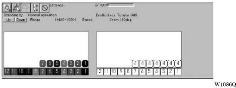
Changing individual range
- Double-click the range display.
- Click a speed range for selection.

- Click [OK].
Grid Setting
Sets the pitch and the color of grid.
■The grid interval can be set at the increment of 1 mm (0.1 inch for inch unit).
■The value for setting is 1 - 100 mm (0.1 - 10 inches for inch unit).
- Select [Grid setting] from the View menu.
![controller - [ECMS] View Tool Settings Window Tool Bar Status Bar Zoom In Zoom Out Zoom In Specified Range Edit to window Whole Pattern Grid Hoop Hoop Position Needle Penetration Thread Color Needle Bar and Speed Range Grid Setting Back ground Color](/content/2026/05/1004755/images/9987856f115ae32f8802b8da332b07fca2c952d95ce06c9071b098792af58347.jpg)
W1088Q
- Set the pitch.
Click the [color] to change the grid color. For setting, refer to steps 5 to 7 in page 6-16.
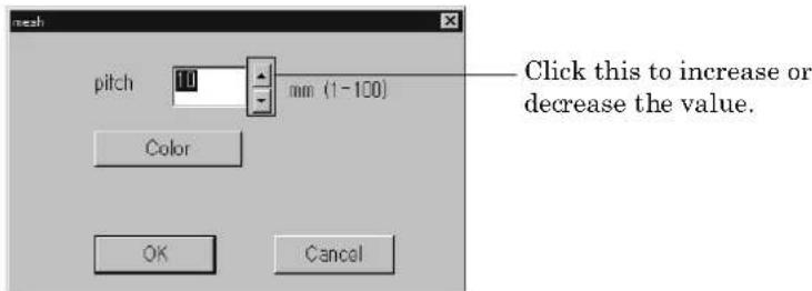
W1089Q
Background color
Changes the background color of the data.
- Select [Background color] from the [View] menu.
![controller - [ECM3] View Tool Settings Window Tool Bar Status Bar Zoom In Zoom Out Zoom In Specified Range Edit to window Whole Pattern Grid Loop Loop Position Needle Penetration Thread Color Needle Bar and Speed Range Grid Setting Back ground Color](/content/2026/05/1004755/images/3e519e986cc3b1a4f038ed0234802242a1fbf1988c530d490d9175121ec48800.jpg)
W1090Q
- Select or create the background color.
Refer to steps 5 to 7 on page 6-16 for details.

natural_image
Black-and-white line drawing of a floral arrangement in a basket, enclosed in an octagonal frame (no text or symbols)
natural_image
Black-and-white illustration of a potted plant with stems and leaves, enclosed in an octagonal frame (no text or symbols)Before changing the background color After changing the background color W1091Q W1092Q
Renaming Machine
Rename the registered machine.
■Up to 50 characters can be registered for a machine name.
- Select [Rename Machine] from Machine menu.
- Enter a new name.

Select an identifying color for the machine. This color is shown on the title bar for a while when the arrow pointer is moved to the title bar of a machine window.
W1093Q
- Click [OK].
If the message "The entered name already exists" appears, enter another name.
Viewing Machine Information
Detail specification of the machine can be displayed.
- Select [Machine Information] from Machine menu.
- Click [OK] after checking the information.
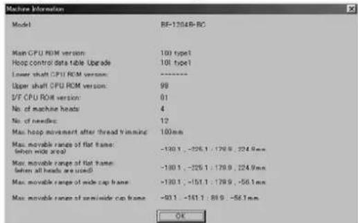
W1094Q
Design Information
Detail specification of the embroidery data can be checked.
| Pattern name File name and path of embroidery data |
| No. of stitches The number of stitches in embroidery data |
| No. of colors The number of colors used in embroidery data |
| Mask Size Size of masking |
| Start of Embroidering Coordinates of embroidering start position |
| End of Embroidering Coordinates of embroidering end position |
- Select [Design Information] from Help menu or click

- After checking, click [OK].
Setting Window Display
Specifies the window that displays machine condition if multiple machines are connected simultaneously.
■There are two types of window display as follows:
| Cascade Windows are slightly offset. |
| Tile Windows are tiled. |
- Select [Cascade] or [Tile] from Window menu.

When [Cascade] is selected When [Tile] is selected W1096Q W1097Q
Minimizing and Aligning Windows
Windows on the screen can be minimized to the icon size and aligned.
Minimize Window Size
- Select [Minimize Window Size] from Machine menu or click _ on the upper right corner of the screen.

- The window is minimized.

Arrange Icons
Minimized windows that are scattered can be aligned.
■This command is available for minimized windows.
- Select [Arrange Icons] from Window menu.
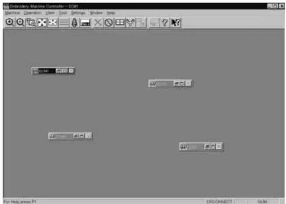
W1100Q
- The minimized windows are aligned.

W1101Q
Changing window size
Several square buttons with figures are displayed at the right end of the title bar. These buttons are used to change the window size.

If this button is clicked when running an ordinary software, it is displayed on the task bar in the minimized size as a button.

If this button is clicked, the window size changes to a medium size.

If this button is clicked, the window changes to the full size of the desktop.

This button is used to end the software or to close the folder. This button cannot be clicked when the machine window is displayed.
Language
Changes display language.
Refer to page 6-8.
Copying Data to Other Machines
When multiple machines are connected, the embroidery data of a machine can be copied to another machine.
- Click the window of the machine displaying the copy source data.

- Click

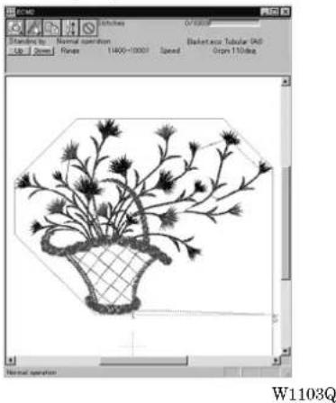
natural_image
Illustration of a floral basket with dried flowers, displayed within an image editing software interface (no text or symbols on the diagram itself)- Click and select the machine name of the destination.
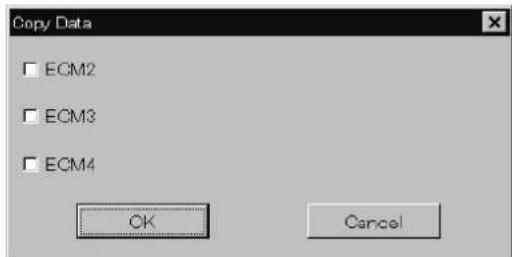
W1104Q
4. Click [OK].

The data, is copied.
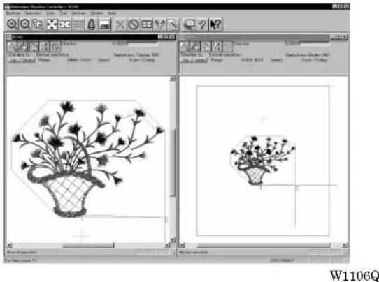
Configuration
Sets the environment of data reading and display.
- Select [Configuration] from Tool menu.
- Click and select the item for setting.
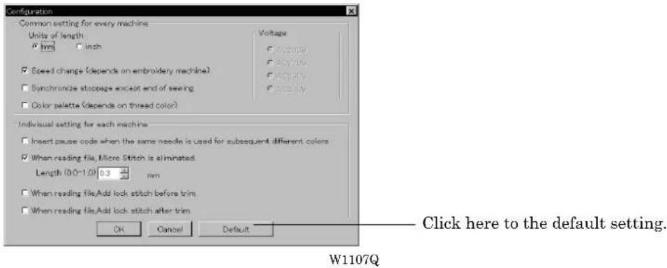
[When reading file, Micro Stitch is eliminated.] is set to be deleted in default status (checked).
3. Click [OK].
Upgrading the Machine Program
Upgrades the programs at each part of the machine.
This function is protected by a password. A dealer engineer will use this function if required.
Setting the Machine
Performs the detail setting of the embroidering status. Items that can be selected in Setting menu are explained here.
Needle Bar
Patterns are sewn by one needle.
-
Select the [Needle]-[Same Needle] from Settings menu.
-
Click the needle number for selection.
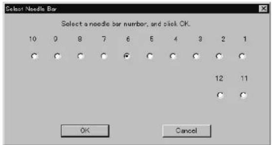
W1108Q
- Click [OK].
The embroidering sequence appears at all specified needle points.
![Embroidery Machine Controller - [DCMS] Machine Operation View Tools Settings Window Help Statches Standard by Normal operation Up Down Range 1400-800 Speed Basket area Burder (AB) Open 11/02/03 Open 11/02/03 1 2 3 4 5 6 7 8 9 10 11 12 13 14 15 16 17 18 19 20 21 22 23 24 25 26 27 28 29 30 31 32 33 34 35 36 37 38 39 40 41 42 43 44 45 46 47 48 49 50 51 52 53 54 55 56 57 58 59 60 61 62 63 64 65 66 67 68 69 70 71 72 73 74 75 76 77 78 79 80 81 82 83 84 85 86 87 88 89 90 91 92 93 94 95 96 97 98 99 100](/content/2026/05/1004755/images/b13368743956bb8e41fd52b7df2a89adf4aaf5643d3c67abc3a12997a131915c.jpg)
W1109Q
Default setting (equating the sewing order number and needle bar number)
- Select [Needle] - [Default value] from Settings menu.
Same Speed Range
Embroiders patterns at the specified speed range.
-
Select [Same Speed Range] from Settings menu.
-
Click a speed range for selection.

W1110Q
- Click [OK].
The speed range appears at the specified areas.
![Embroider Machine Controller - [ECM] Machine Operation View Text Settings Window Help Stitches Normal operation Back to east Border AID Up to Down Paper 2400-8001 Speed Dryn 110lbs 10 9 8 5 4 3 2 1 2 1 0 7 6 5 4 3 2 1 Pango 3 needed For this sheet F1 SINCOMMENTS](/content/2026/05/1004755/images/7e6df81ea3f5718e182cf223b744d9d650423d7ce4213fe56d1fac19ac4d7fc3.jpg)
W1111Q
Pause
Sets whether to stop the needle bars temporarily when changing all the needle bars.
Stopping all the needle bars temporarily
- Select [Pause] - [Add all] from Settings menu.
Resetting temporary stop of all the needle bars
- Select [Pause] - [Delete all] from Settings menu.
Speed Range
Specifies the maximum speeds for respective ranges suitable for the hoop type.
■Actual embroidering speed depends on the pitch.
■ Before shipment, "1" is set to the highest speed; "6" is set to the lowest speed.
-
Select [Speed Range] from Settings menu.
-
Specify the desired range.
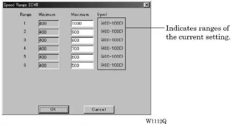
When a value exceeding the above ranges is entered, it is automatically set to the min. or max. speed.
- Click [OK].
Head Operation Suspend
Sets the machine head for rest.
■Setting at the machine head has priority.
■ When the HEAD switch at the machine head is set to ON and then to OFF, the setting is canceled.
-
Select [Head Operation Suspend] from Settings menu.
-
Click the machine head that needs to be at rest and remove the check mark.
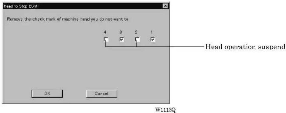
- Click [OK].
Hoop Feed Position
Set the basic position of the hoop (hoop feed position) for cancellation of embroidering.
■ The hoop feed position can be set only in the embroidering area surrounded by a red frame.
■ The hoop feed position can not be set in the upper side of the frame when [Tubular] is selected in [Embroidery hoop] and the frame is displayed on the screen.
-
Select [Hoop Feed Position] from Settings menu.
-
Click the point to feed the hoop.

- The gray cross appears and shows the hoop feed position.
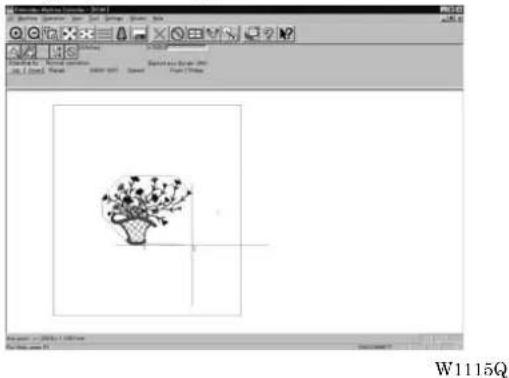
natural_image
Illustration of a potted plant with flowers, displayed in a graphics editing interface (no text or symbols on the plant itself)Embroidery Area
Sets the embroidery area.
- Select [Embroidery Area] from Settings menu.
- Drag the embroidery area using the mouse for designation.

natural_image
Black-and-white line drawing of a potted plant with slender leaves and stems, enclosed in a software interface window (no text or symbols on the plant itself)W1116Q
The embroidery area is displayed in light blue.
Embroidery Hoop
The type of specified embroidery hoop changes the display.
■The kind of the selectable frame varies according to settings at machine side.
■The following selections are available:
| Tubular (All) |
| Flat (All) |
| Border (All) |
| Wide cap (All) |
| Semi-wide cap (All) |
| Mini Flat (All) |
1. Select [Embroidery Hoop] and the type from Settings menu.

W1117Q
The pattern direction and embroidering area may vary depending on the selected embroidery hoop type. Make sure that the selection is correct.
■The following shows the screen example with the frame selected.

natural_image
Simple line drawing of a flower in a basket inside a software interface (no text or symbols on the flower itself)W1118Q
When "Tubular (ALL)" is selected.

The image is displayed upside down. The speed is automatically adjusted to 800 rpm or less.
W1119Q
When "Wide cap (ALL)" is selected.
![24.1.13 Drawing 1: [ ] [ ] [ ] [ ] [ ] [ ] [ ] [ ] [ ] [ ] [ ] [ ] [ ] [ ] [ ] [ ] [ ] [ ] [ ] [ ] [ ] [ ] [ ] [ ] [ ] [ ] [ ] [ ] [ ] [ ] [ ] [ ] [ ] [ ] [ ] [ ] [ ] [ ] [ ] [ ] [ ] [ ] [ ] [ ] [ ] [ ] [ ] [ ] [ ] [ ] [ ] File Edit View Insert View Help [1] 100% 100% 100% 100% 100% 100% 100% 100% 100% 100% 100% 100% 100% 100% 100% 100% 100% 100% 100% 100% 100% [1] 100% 100% 100% 100% 100% 100% 100% 100% 100% 100% 100% 100% 100% 100% 100% [1] 100% 100% 100% 100% 85% [1] 100% 100% 100% 85% [1] 100% 100% 85% [1] 100% 100% 85% [1] 100% 100% 85% [1] 100% 100% 85% [1] 100% 100% 85% [1] 100% 100% 85% [[1] 100% 85% [2] 100% 85% [3] 100% 85% [4] 100% 85% [5] 100% 85% [6] 100% 85% [7] 100% 85% [8] 100% 85% [9] 100% 85% [10] 100% 85% [11] 100% 85% [12] 100% 85% [13] 100% 85% [14] 100% 85% [15] 100% 85% [16] 100% 85% [17] 100% 85% [18] 100% 85% [19] 100% 85% [20] 100% 85% [21] 100% 85% [22] 100% 85% [23] 100% 85% [24] 100% 85% [25] 100% 85% [26] 100% 85% [27] 100% 85% [28] 100% 85% [29] 100% 85% [30] 100% 85% [31] 100% 85% [32] 100% 85% [33] 100% 85% [34] 100% 85% [35] 100% 85% [36] 100% 85% [37] 100% 85% [38] 100% 85% [39] 100% 85% [40] 100% 85% [41] 100% 85% [42] 100% 85% [43] 100% 85% [44] 100% 85% [45] 100% 85% [46] 100% 85% [47] 100% 85% [48] 100% 85% [49] 100% 85% [50] 100% 85% [51] 100% 85% [52] 100% 85% [53] 100% 85% [54] 100% 85% [55] 100% 85% [56] 100% 85% [57] 100% 85% [58] 100% 85% [59] 100% 85% [60] 100% 85% [61] 100% 85% [62] 100% 85% [63] 100% 85% [64] 100% 85% [65] 100% 85% [66] 100% 85% [67] 100% 85% [68] 100% 85% [69] 100% 85% [70] 100% 85% [71] 100% 85% [72] 100% 85% [73] 100% 85% [74] 1O [[O]]](/content/2026/05/1004755/images/956930a841de87af67578d3702374fd1b13c475a31a84c2416e53655529b9bcb.jpg)
The image is displayed upside down. The speed is automatically adjusted to 800 rpm or less.
W1120Q
When "Semi-wide cap (ALL)" is selected.
Thread Trimming
■The following items can be set:
| Enable inching Sets inching motion for thread trimming. | |
| Hoop movement after thread trimming | Sets the needle penetration length for trimming.The length can be set in inches. To set the length in inch unit, select [Inch] from the [Configuration] of Tool menu.The available values are as follows:For mm 0 - 100 mm (The standard value is 15 mm.)For inch 0 - 3.9 inch (The standard value is 0.6 inch.) |
| Thread length (1-10) for all machines | Sets the overall thread amount through the needle.Value of 1 to 10 can be set. The smaller the value is, the shorter the length is. |
| Thread length after thread trimming | Sets the overall thread amount through the needle.Value of 1 to 10 can be set. The smaller the value is, the shorter the length is. |
-
Select [Thread Trimming] from Settings menu.
-
Set inching, thread length, etc.

W1121Q
- Click [OK].
Thread Breakage Sensor
The sensor for thread breakage can be turned ON/OFF or the sensor sensitivity for each needle bar can be set.
■ The sensitivity can be set within the range of 1 - 100. The smaller the value is, the higher the sensitivity is.
-
Select [Thread Breakage Sensor] from Setting menu.
-
Click the head you want to disable the sensor and remove the check mark (√).

W1125Q
- Adjust the sensor sensitivity.
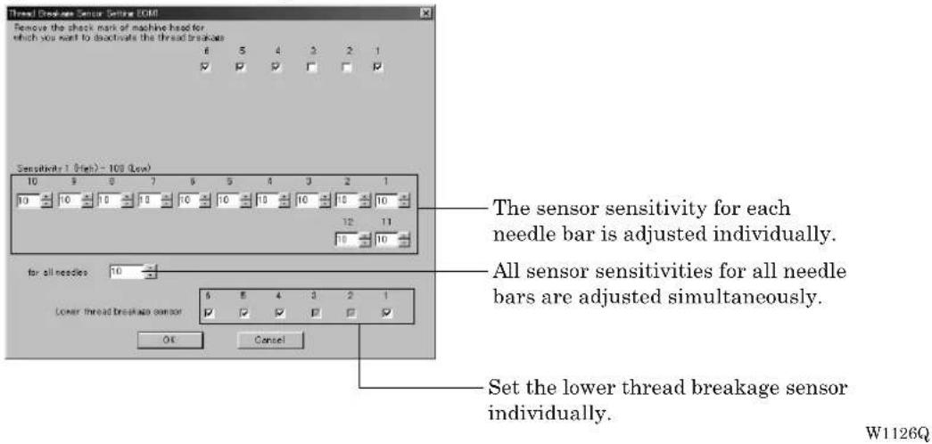
- Click [OK].
Automatic Step Back
Sets the number of stitches for automatic step back if thread breakage occurs.
■The number of stitches that can be set is from 0 to 255.
■Additional step-back can be made for sensitivity value of the thread breakage sensor.
-
Select [Automatic Step Back] from Settings menu.
-
Enter the number of stitches for automatic step back.

- Click [OK].
Automatic Hoop Feed
Sets automatic hoop feed for a thread breakage.
- Select [Automatic Hoop Feed] from Settings menu and put the check mark (√).
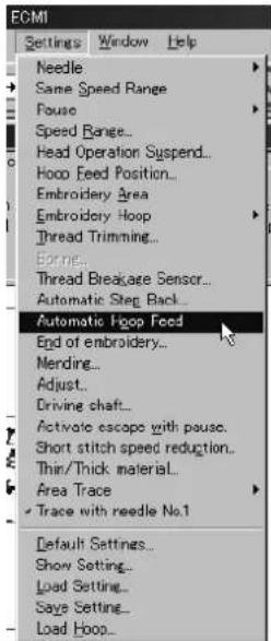
W1128Q
End of embroidery
Sets if the machine returns to the start point after end of embroidery.
- Select [End of embroidery] from Settings menu.

W1129Q
- Click the checkbox to put a check mark (√) when the machine returns to the start point after end of embroidery. Click [OK].
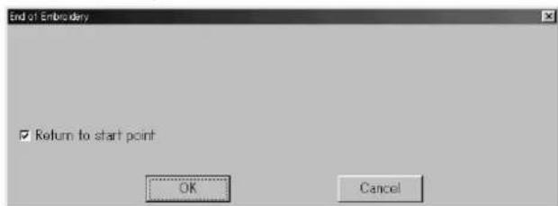
W1130Q
Mending
Sets the details of mending.
■Items and descriptions are as follows:
| Automatically reset breakage error Error is automatically canceled when a thread breakage occurs. | |
| Thread entangled error to rotary hook Selects how to reset the rotary hook thread entanglement error. | |
| After the end of mending Sets whether to stop or suspend the needle bar at the mending end position. | |
| Raise the presser foot when clearing a thread trimming error | Raises the presser foot when resetting the thread trimming error. |
| Stitches before mending Sets the number of stitches for stopping before mending.The values for setting are 1 - 10. | |
| When the machine is stopped Selects how the trimming is made during stopping. | |
| Insert lock stitch at the beginning of sewing after thread breakage | Automatically conducts lock stitch when trimming thread. |
- Select [Mending] from Settings menu.

W1131Q
2. Click [OK] when the items are set.
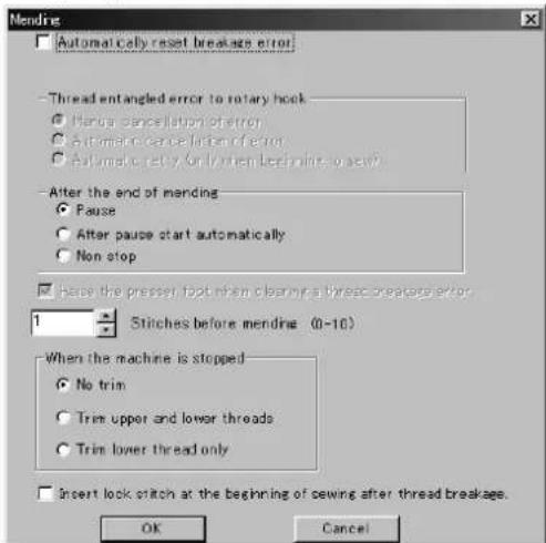
W1132Q
Manually trim the lower thread immediately after resetting a thread breakage error if feeding by stitch back is long (i.e., 40 to 50 mm or more) when "After the end of mending" is set to "Non stop". Set "When the machine is stopped" to "Trim lower thread only".
Adjust
Adjustment value of the needle is set.
■The adjustment value is set at the increment of 0.1 mm.
■The setting range is -0.5 \~ 2 mm in X and Y directions.
1. Select [Adjust] from Settings menu.
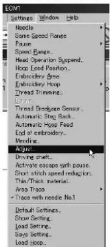
W1133Q
2. When setting is complete, click [OK].

W1134Q
Driving shaft
Speeds up the startup of the main shaft. Select this function when sewing thick material.
- Select [Driving shaft] from Settings menu and check it.
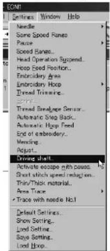
W1135Q
- When the item selection is completed, click [OK].
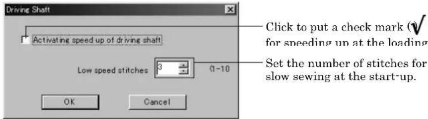
W1137Q
Activate escape with pause
Sets whether to feed the hoop during temporary stop of the needle bars to change colors. Select this function when embroidering applique.
- Select [Activate escape with pause] from Settings menu and check it.

W1136Q
Short stitch speed reduction
Reduces speed when stitching in a designated pitch.
■The pitch can be designated between 0.0 and 2.0 mm in units of 0.1 mm.
■ The speed can be set between 400 rpm and the maximum speed of the current hoop in units of 10 rpm.
- Select [Short stitch speed reduction] from Settings menu.
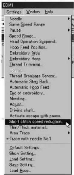
W1138Q
- Click [Reducing speed] to check it and click [OK] when items are set.

W1139Q
Thin / Thick Material
Adjusts the timing of needle drop and hoop movement.
The value can be designated between 95 and 125 degrees (85 and 115 degrees for cap frame) in units of 1 degree. The smaller values are suitable for thick material and the larger ones are suitable for thin material.
- Select [Thin / Thick material] from Settings menu.

W1140Q
- Adjust the value by moving the slide bar control. Click [OK] when it is set.

W1141Q
Area Trace
Select the outside shape of area tracing before starting sewing.
■ The following two types can be selected. The selected outside shape is displayed on the screen.

natural_image
Black-and-white illustration of a floral basket with leaves and stems, displayed within an image editing software interface (no text or symbols on the main image)Rectangle Octagon

natural_image
Black-and-white line drawing of a flower in a basket, enclosed in an octagonal frame (no text or symbols)W1142Q W1143Q
- Select the outside shape of [Area trace] from Settings menu and check it.

W1144Q
Trace with needle No. 1
Change the current needle bar to No. 1 and start the area tracing.
- Select [Trace with needle No. 1] from Settings menu and check it.

W1145Q
Default Settings
Resets changes of the machine setting to the default.
■Items for setting and initialization are as follows:
| Speed Range Automatically selects the value suitable for the hoop type. | ||
| Head Operation Suspend Cancels the head operation which is not set for rest on the machine. | ||
| Hoop Feed Position Returns to the machine home position. | ||
| Embroidering Area Sets the size each for the selected hoop. | ||
| Thread Trimming | Inching motion | Yes |
| Thread removal feed length | 15 mm (0.6 inch) | |
| Thread remaining amount | 5 | |
| Thread Breakage Sensor | All sensors are on.Sensitivity 10 | |
| Automatic Step Back 0 | ||
| Thread BreakageSensor Sensitivity | Not affected by the thread breakage sensor sensitivity | |
| Automatic Feed Hoop No | ||
| Return to the start point Yes | ||
| Mending Automatically rest breakage error | No | |
| No | ||
| Yes | ||
| Yes | ||
| 1 stitch | ||
| No | ||
| No | ||
| Adjustment | 0.0 mm for X direction0.0 mm for Y direction | |
| Main shaft speed up setting | Activating speed up of driving shaft Low speed stitches | No3 |
| Hoop feed during temporary stop | No | |
| Reducing speed in a small pitch | No | |
| Thin / Thick material | 110 degrees (100 degrees for cap frame) | |
| Area Trace | "8 corner" is selected. | |
| Trace with needle No.1 | Yes | |
1. Select [Default Settings] from Settings menu.

W1146Q
2. Click [OK].
Show Setting
Shows the setting contents and defaults.
■The following items are shown:
- Embroidery area
- Enable inching
• Hoop movement after thread trimming - Sensitivity
- Backward steps
• Automatic hoop feed - Return to the stant point
- Activating speed up of driving shaft
- Slow stitch times
1. Select [Show Setting] from Settings menu.

W1147Q
2. After checking, check [OK].
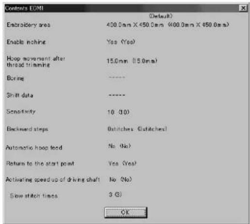
W1148Q
Load Setting
Load the setting.
■The set file has an extension of "ecm".
- Select [Load setting] from Settings menu.

W1149Q
- Select the folder and click [Open].

W1150Q
Save Setting
Saves the edit settings.
■Save the setting files with an extension of "ecm".
- Change the setting.
- Select [Save setting] from Settings menu.

W1151Q
- Select the registration folder and put a file name.
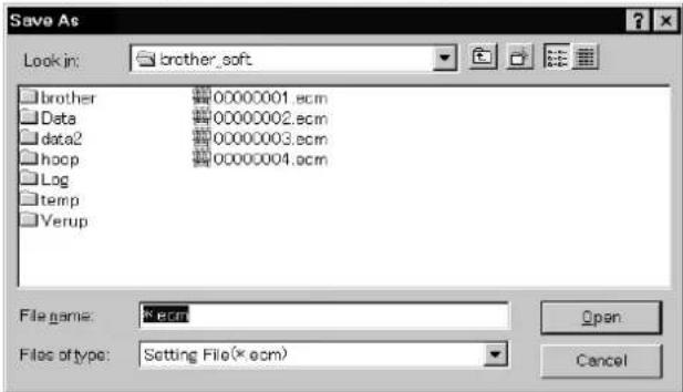
W1152Q
- Click [Save].
Load Hoop
Load the optional hoop displayed in "Hoop".
■The hoop file to be loaded has an extension of "ehp".
■The types and the shapes of hoop for loading are as follows:
Round frame
| ROUND_FRAME21.ehp |  | ROUND_FRAME25.ehp |  |
| W0839Q | W0840Q |
Square frame
| SQUARE_FRAME24X24.ehp |  W0841Q W0841Q | SQUARE_FRAME40X43.ehp |  W1548Q W1548Q |
| SQUARE_FRAME45X23.ehp |  W0842Q W0842Q | SQUARE_FRAME45X27.ehp |  W0843Q W0843Q |
Spider net frame
| SPIDER_NET_FRAME05B-1.ehp |  W0845Q W0845Q | SPIDER_NET_FRAME07B-1.ehp |  W0853Q W0853Q |
| SPIDER_NET_FRAME07T-1.ehp |  W0849Q W0849Q | SPIDER_NET_FRAME09T-1.ehp |  W0857Q W0857Q |
| SPIDER_NET_FRAME10B-1.ehp |  W0861Q W0861Q | SPIDER_NET_FRAME12T-1.ehp |  W0865Q W0865Q |
| SPIDER_NET_FRAME13B-1.ehp |  W0869Q W0869Q | SPIDER_NET_FRAME15T-1.ehp |  W0873Q W0873Q |
| SPIDER_NET_FRAME16B-1.ehp |  W0877Q W0877Q | SPIDER_NET_FRAME18T-1.ehp |  W0881Q W0881Q |
| SPIDER_NET_FRAME19B.ehp |  W0885Q W0885Q | ||
| Tubular frame | |||
| TUBULAR_FRAME-05.ehp | W0886Q | TUBULAR_FRAME-07.ehp |  W0887Q W0887Q |
| TUBULAR_FRAME-10.ehp |  W1549Q W1549Q | TUBULAR_FRAME-13.ehp |  W1550Q W1550Q |
| TUBULAR_FRAME-10R.ehp |  W0888Q W0888Q | TUBULAR_FRAME-13R.ehp |  W0889Q W0889Q |
| TUBULAR_FRAME-16.ehp |  W0890Q W0890Q | TUBULAR_FRAME-19.ehp |  W0891Q W0891Q |
| TUBULAR_FRAME23X24.ehp |  W0892Q W0892Q | TUBULAR_FRAME23X43.ehp |  W0893Q W0893Q |
| TUBULAR_FRAME26X43.ehp |  W0894Q W0894Q | TUBULAR_FRAME30X28.ehp |  W1551Q W1551Q |
| TUBULAR_FRAME30X28P500.ehp |  W1552Q W1552Q | TUBULAR_FRAME30X30.ehp |  W0895Q W0895Q |
| TUBULAR_FRAME30X43.ehp |  W1553Q W1553Q | TUBULAR_FRAME40X43.ehp |  W1554Q W1554Q |
| Holder base frame | |||
| HOLDER_BASE23X24.ehp |  W0899Q W0899Q | HOLDER_BASE23X43.ehp |  W0900Q W0900Q |
| HOLDER_BASE30X28.ehp |  W0901Q W0901Q | HOLDER_BASE30X43.ehp |  W0902Q W0902Q |
Tubular round frame
| TUBULAR_ROUND07.ehp |  | TUBULAR_ROUND09.ehp |  |
| W0905Q | W0906Q | ||
| TUBULAR_ROUND12.ehp |  | TUBULAR_ROUND15.ehp |  |
| W0907Q | W0908Q | ||
| TUBULAR_ROUND18.ehp |  | TUBULAR_ROUND24X24.ehp |  |
| W0909Q | W0910Q | ||
| TUBULAR_ROUND24X30.ehp |  | TUBULAR_ROUND32X45.ehp |  |
| W0911Q | W0913Q |
Cap frame semi-wide frame
| CAP_FRAME_SEMI_WIDE.ehp |  W0915Q W0915Q |
| Cap frame wide frame | |
| CAP_FRAME_WIDE.ehp |  W0916Q W0916Q |
1. Select [Load hoop] from Settings menu.
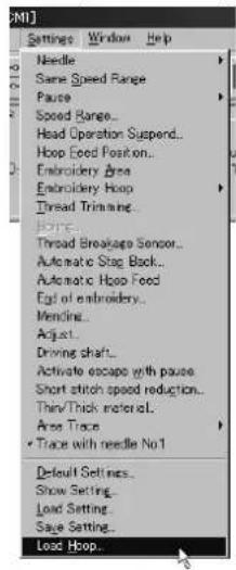
W1153Q
2. Select the folder and click [Open].

W1154Q
Embroidering
How to start embroidering and operation after the start are explained here.
Starting Embroidering
■The following screen appears when the edit data is retrieved from the explorer.

W1155Q
1. Click .

When sewing start position differs from current needle position, "Hoop" appears at the machine display window.
Click 📋 to move the hoop to the sewing start position.
2. Press the button.
Embroidering starts.
Embroidery data appears in gray, indicating the embroidering status.
![Emerson: Marine Controller - [BICM] Balance Operation Item Test Settings Window View Entropology, Normal operation 10000-900 Seed 1000gm/150mg Stable out Border (A) Up / Down Place Normal operation For help, use F1 December 27](/content/2026/05/1004755/images/8467c63f6b247f3c763961e89243e049ff05e2fd17f6feb173b69d8ec5e56353.jpg)
W1156Q
Pause
- Click

Canceling
- Press the

button while pressing the button on the machine operation panel.
- Click

- The check screen appears. Click [Yes] to cancel.
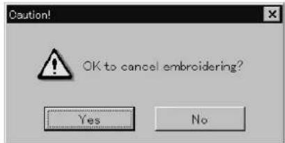
W1157Q
Moving the Home Position
Move the selected machine home position.
- Select [Home Position] from Operation menu or click .
Step-forward/Step-back
Allows step-forward or step-back of stitches without embroidering.
■Click ☑ to stop embroidering for step-forward/back mode.
■The special tool bar appears in the step-forward/back mode.

Entering in the Step-forward/Step-back Mode
-
Click to stop embroidering.
-
Select [Step F/B] from the Operation menu or click

A cross appears on the screen. The current needle position is the intersection of the vertical and horizontal lines.

W1159Q W1160Q
Canceling step-forward/step-back
- Click ✗ of the step forward/back tool bar.
The cross disappears and the step forward/back mode is canceled.

natural_image
Black-and-white illustration of a flowering plant with slender branches and small leaves, displayed within an image editing interface (no text or symbols on the plants themselves)W1160Q
Setting Step-forward/Back Distance or Timing
Select step-forward/back distance or timing.
■The functions of icons are as follows:

W0926Q
| 1 | Moves forward (backward) by 1 stitch. |
| 10 | Moves forward (backward) by 10 stitches. |
| 100 | Moves forward (backward) by 100 stitches. |
| ^ | Moves to the next (previous) color change. |
| ^ | Moves to the next (previous) feed. |
- Click the icon to select the desired function.
Stepping Forward/Back
Steps forward/back the stitches actually.
■The functions of icons are as follows:

W0927Q
| S◀ | Returns to the start position. For repeating patterns, returns to the start position of the current pattern. |
| ◀◀ | Moves backward by the specified distance continuously. Click ▶ stop movement. |
| ◀◀ | Moves backward by the specified distance. |
| ■ | Click this to stop after clicking ⏻ . ▶ |
| ▶▶ | Moves forward by the specified distance. |
| ▶▶ | Moves forward by the specified distance continuously. Click ▶ stop movement. |
| ▶▶ | This is selected for repeating patterns. The machine goes to the start position of the next pattern. |
| Specify the travel length from the embroidery start point. |
■Selection of movement to the start position. The needle moves as follows:

Click the icon and the needle moves to the start position of the current
W1162Q


Click the icon and the needle moves to the start position of the next repeating pattern.

W1163Q W1164Q
- Select the icon and move the cross to the desired position for step forward/back.

natural_image
Black-and-white line drawing of a plant with dried flowers in a basket, displayed within a software interface (no text or symbols on the diagram itself)Forward Backward
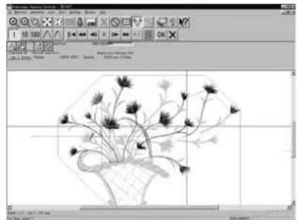
natural_image
Black-and-white line drawing of a plant with dried flowers in a basket, displayed within a software interface (no text or symbols on the diagram itself)W1165Q W1166Q
Specifying the Value
Specify the travel length from the embroidery start point.
- Click

- Input the number of stitches to start embroidery. Click [OK].

W1167Q
Resuming Embroidering
- Click in the tool bar.
The cross disappears. The embroidery status at the step forward/backward position of the stitches is displayed.

natural_image
Illustration of a potted plant with slender leaves and stems, enclosed in an octagonal frame (no text or symbols)Forward Backward
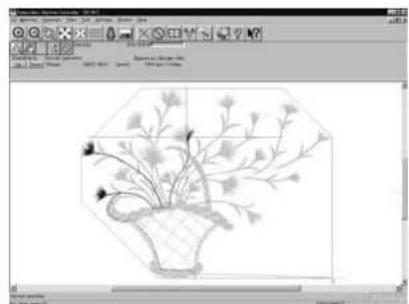
natural_image
Illustration of a potted plant with flowers and leaves inside a hexagonal frame (no text or symbols)W1168Q W1169Q
- Click .
It is ready to resume embroidering and "Hoop" appears at the machine display window.
- Press on the machine.
Moving Embroidery Position
Changes the position of embroidery data.
■Movement is allowed only in the embroidering area (within the red frame).
- Select [Move Embroidery Position] from Operation menu or click

![Embroidery Manager Controller - [30141] File Edit View Insert Settings Window Help Normal operation View Insert Settings Window Help Standard: Normal operation Page 11/00-0027 Save Backframe Border (A) From 1716kg Embroidering area Normal operation File Edit view Insert W1170Q](/content/2026/05/1004755/images/6fd13bda945e89f299c10a75e07dfba3a816e4773810c896b3d80b53de50a4db.jpg)
- The pointer turns into . Drag the embroidery data.
The mouse arrow becomes + while dragging.
![3D Manager Machine Controller - [3D.M] File Edit View Insert Settings Window Help Edit(X) Edit View Insert Settings Window Help Ctrl+X Normal operation 1000-9000 Screw Resistently Border (M) Organ:110kg 40 x 5.25 kg x 5.275 mm For Help sheet (F)](/content/2026/05/1004755/images/d55d138b6a61316f41ac3a881a0ddc436c4247bcc13fc17715dbda31eed7ac8b.jpg)
W1171Q
Centering Pattern
Moves the pattern to the machine home position.
- Select [Move Pattern] from Operation menu.

W1172Q
- The pattern is moved.
![Embrace Machine Tools - [07-1] File Edit View Insert Tools Settings Window Help Name: Image Material Information Color: 100% Size: 5 px Balance/Number 14x Draw Time Normal position For help, select (F)](/content/2026/05/1004755/images/56ee5a91d2dc98668089a3be5cf4c4cd9c1e381f81b60706c460c484baa55598.jpg)
W1173Q
Saving Data
Saves the edited data. The edited data can be saved over the current file or renamed as a separate file.
Save
Saves the edited data over the current file. The original data is deleted.
- Select [Save] from File menu or click

- If color etc. has been is changed, the pattern image appears.
Save As...
Renames and saves the edited data as a new file.
-
Select [Save as...] from File menu.
-
Select the directory to save the new file. Enter a new file name.

W1174Q
-
Click [Save].
-
If color etc. has been is changed, the pattern image appears.

W0744Q
Test
Carries out sensor information check, actuator operation test, test for main shaft rotation, etc. for machine maintenance.
This function is protected by a password. A dealer engineer will use this function if required.
Running Other Programs
Other programs can be started when the machine power is not turned on or when the machine is in operation for embroidery.
■The following programs can be started:
Embroidery data explorer Allows transfer and copy of the embroidery data. Data transfer to the machine controller is not allowed.
Embroidery data editor Allows editing of embroidery data.
Production report Allows display and print-out of production data, etc.
1. Select [Embroidery Data Explorer independently] or [Embroidery Data Editor independently] from Tool menu.

W1175Q
Selecting [Embroidery Data Edit Individual Start]
■ Input the number of needle bars. Input the number according to your machine specifications. Click [OK].
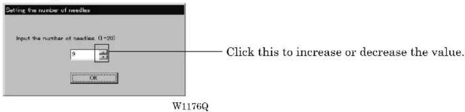
Chapter 7 Operation of Machine
1. Operating Procedures
1-1 Power Source
Main power switch
②

②
Emergency stop switch
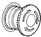
W1262Q W1265Q W1405Q W1266Q
Flat / Cap hoop select swich
Power switch


- Turn on the main power switch.
- Reset the emergency stop switch.
- Change the Flat / Cap hoop select switch according to the hoop to be used.
- Press the power switch.
- The power lamp lights up and the display window indicates "1204" (BE-1206B: "1206")".
BE-1204B-BC BE-1206B-BC
BE-1204C-BC

W1355Q W1356Q
- The alarm sounds three times and the needle bar move upward. Then the hoop moves to the home position and the sewing data screen is displayed.
When turning the power off and back it on again, wait for at least 10 seconds.
1-2 Preparation for Embroidering
- Select embroidering data while the machine is in the waiting state for an embroidering data selection, and transmit required data by pressing the 🧑icon.
- The READY lamp lights up and the machine is placed in the waiting state.
- Pressing ◀ ▷ △ ▽, determine a position to start embroidering.
An error code is displayed in the display window if a pattern comes out of the hoop.
- Pressing starts embroidering.
During embroidering, the speed is indicated in the display window.
- After embroidering is finished, the machine is placed in the stand-by state.
2. Machine Stop
2-1 Stopping the Machine
Stop switch

O STOP
W1267Q
Press the stop switch or STOP stop the operation of the machine.
2-2 Emergency Stop of the Machine

natural_image
Diagram of a mechanical component with rotational arrows indicating motion (no text or symbols)W1269Q
When the emergency stop switch is pressed, all power except that for the fluorescent lamp is turned off.
2-3 Resetting Emergency Stop
Emergency stop switch

W1265Q W1266Q
Power switch

When turning the emergency stop switch in the direction of the arrow illustrated on the switch, the knob of the switch pops up and emergency stop is reset.
Press the power switch to turn on the power again.
3. Permission for Hoop Movement
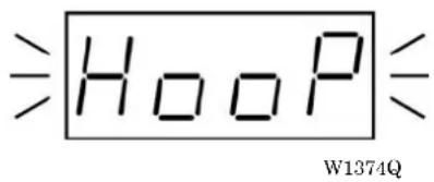
- When the computer has given a command to move the embroidery hoop, "HOOP" is displayed while blinking on the operation panel.
- Press and the embroidery hoop moves to the designated position.
4. Measures against Thread Breakage
4-1 Remedies

W1258Q
- If embroidering is suspended due to thread breakage, the Thread tension base lamp of the machine head blinks in red.
- Correct the broken thread and pass it through again.
Refer to "Chapter 2, 3-1 Upper Threading" (→ Page 2-17) for details.
- Press the STOP switch or press the STEP BACK/FWD switch at machine head in order to reset the alarm.
- Return the hoop to a position where thread breakage occurred by pressing the STEP BACK switch.
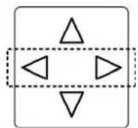
or



W1271Q
When the switch is pressed for 5 stitches or more, the machine continues operation without holding the switch. To stop the machine, press the switch to the opposite side.
- Press the switch on the operation panel or the start switch located between the machine heads to resume operation.

W1270Q
4-2 Mending
In case that a head stops for some reasons such as thread breakage, only the stopped head will retry sewing by specified number of stitches when the head is recovered, and after that, all the heads will restart normal sewing.

W1258Q
This function works in the following procedure:
- In case of an error such as thread breakage, the thread tension stand lamp blinks red and the sewing will be stopped. The other thread tension stand lamps with other heads illuminate green.
- The head with the error will restart sewing from specified position. Heads with no thread breakage are suspended during that period.
- When the stitches reach the position of the thread breakage, all the heads will restart the sewing. However, heads already set to suspension are excluded.
Manual operation of the mending
Setting or cancellation of the mending can be specified during the suspension of embroidering with individual heads regardless of thread breakage.
- End positions of the mending can not be individualized according to head.
If there are more than one heads with the mending function ON, the head position which was set first will be the end position for all heads. -
To cancel the end position, turn ON the mending function (the lamp illuminates green) to all the heads sewing at that time.
-
While the embroidering is suspended with the head to set the mending, flip up its thread tension stand switch further.
The thread tension stand lamp will illuminate green and the mending will be set ON.
To turn OFF the mending, flip up the thread tension stand switch again to turn off the lamp.

W1259Q
- Bring back the needle position by pressing ◀▷ or □ □. The section between the brought back position and the suspended position will be the subject to the mending.
Case of Mending usage

flowchart
graph TD
    A["Sewing direction"] --> B["Stand by position A"]
    B --> C["No.1 Stitch No.2 Stitch No.3 Stitch"]
    C --> D["No.3 Disable mending"]
    D --> E["Stand by position A"]
    E --> F["No.1 Stitch No.2 Stitch No.3 Stitch"]
    F --> G["Mending"]
    G --> H["End"]
-
Disable MENDING function of No. 3 at the standby position A. (This position should be the mending end position.)
-
Press the jog ◀ switch or □to move □it backward.
Disable MENDING function of No. 2 at the position B.
(The position B does not become the end position; the position A remains the end position.)
When enabled MENDING function of the machine head whose MENDING function is disabled:
- The thread tension stand lamp will illuminate green, and mending is executed for the machine head.
5. Jog Embroidering

W1270Q
- Jog embroidering can be used for preventing the thread from slipping from the needle at the start of embroidering.
- Jog embroidering can be executed as long as the start switch at the machine head is held down. Never apply a tape on the switch to keep jog operation for a long time. Doing so may cause damage to the machine.
6. Hoop Feed Position
- In order to ease mounting and dismounting of the embroidery hoop, another needle position can be set as a hoop feed position in the movable area additionally to the current needle position.
- In order to ease material attachment while operation is suspended, the hoop can be moved to the feed position at any time by the hoop feed switch.
- The hoop can also be moved to the feed position automatically after embroidering is finished. Refer to "Automatic Hoop Feed" on Page 6-33 for details.
1. Press

7. Area Check
7-1 External Tracing

W1278Q
If is pressed in other cases than "area over", the rectangular outline of the pattern is traced.
7-2 Automatic Hoop Movement in Area
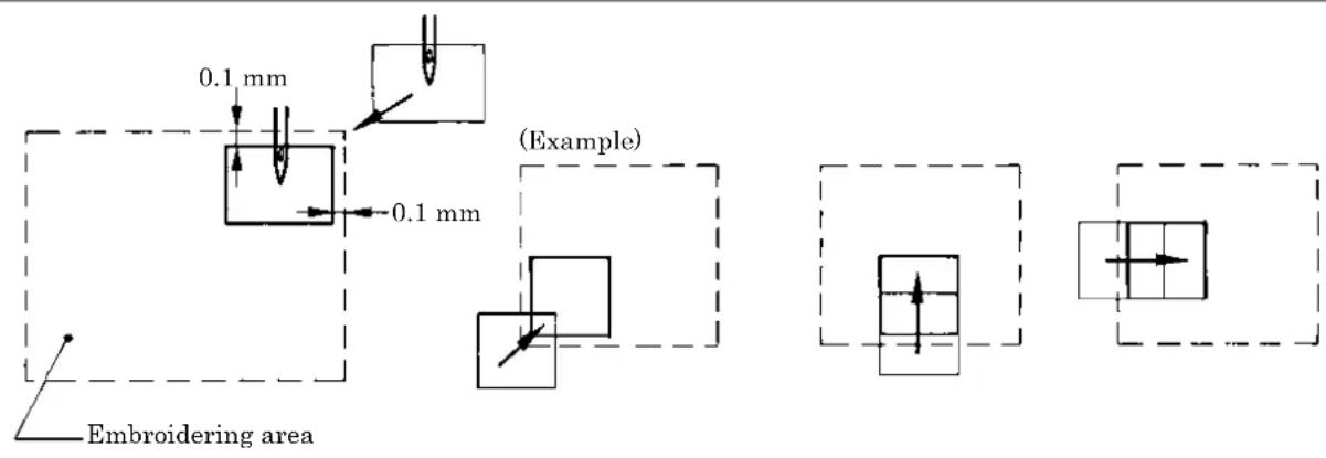
W1279Q
- If "area over" is displayed, press 📄. The hoop automatically moves inside the embroidering area, where the pattern is set, at the nearest position.
- After finishing the movement inside the area by this function, execute external tracing. Then, check that the needle and the presser foot do not interfere with the hoop before starting embroidering.
- If the pattern is not held in the embroidering area as shown below, the hoop cannot move into the area. Enlarge the embroidering area on the operation panel.

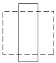
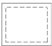
W1281Q
8. Jog Switches
8-1 Hoop Movement to Start Position
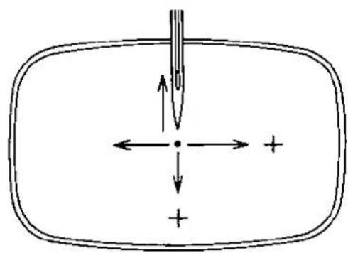
natural_image
Simple line drawing of a rectangular container with internal arrows and a central point, no text or symbols present.W1282Q
The hoop can be moved by pressing ◀ ▷ △ ▽ before starting embroidering and the start position can be set arbitrarily.
8-2 Inching Mode during Embroidering (Forcible Hoop Movement)
- Moving the frame greatly in the inching mode may cause an interference with the machine. Pay utmost care in the inching mode.
- Although the distance of the frame moved in the inching mode is stored even after turning OFF the power, if the power is turned ON again and sewing is started, the pattern may be embroidered in a different position. Be sure to use the inching mode appropriately.

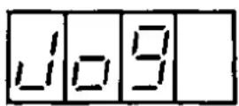
W1375Q W1376Q

W1282Q
- Press while pressing and JST" is displayed.
- Press ▷ to forcibly change the hoop. "JOG" is displayed.
-
Press and press the . The hoop moves to the direction of the pressed switch.
-
Note that the forcible hoop movement will produce deviation of embroidering by the amount.
-
If the hoop and material are deviated from each other during embroidering, correct it by using the jog switches.
-
Pressing ranks the inching mode.
- Press START restarts embroidering.
Chapter 8 Creating Production Report
Records and controls the machine operation. The production report can be created based on this data. Detailed information of production report allows efficient embroidering control.
Functions (Command Reference)
File menu
| Open Report File | [2CWB] | Opens the report file. (→ page 8-4) |
| Save As CSV |  | Saves the current report data in CSV format. (→ page 8-18) |
 | Prints the report. (→ page 8-19) | |
| Print Preview Displays the print preview on the screen. | ||
| Page Setup | Displays the setting screen for printing. (→ page 8-19) | |
| Exit from Production Report Exits from the production report. | ||
Edit menu
| Copy |  | Copies the selected area to the clipboard. (→ page 8-20) |
| Select All Selects all report data. | ||
View menu
| Details |  | Displays detail data. (→ page 8-5) |
| Thread Breakage Information on Needle Bar |  | Displays the thread breakage information for each machine needle. (→ page 8-6) |
| Thread Breakage information in pattern |  | Displays the thread breakage information for each pattern. (→ page 8-7) |
| Output information |  | Displays the production output of each machine. (→ page 8-8) |
| Total output information |  | Displays the total production output. (→ page 8-10) |
| Display graph Displays the information in graph. | ||
| Display text Displays the information in text. | ||
| Top page Displays the top page. |  | |
| Previous page Displays the previous page. | ||
| Next page Displays the next page. |  | |
| Last page Displays the last page. |  | |
| Tool Bar Displays the tool bar. | ||
| Status Bar Displays the status bar. | ||
Settings menu
| Items to be displayed | Sets the display item. (→ page 8-12) |
Description of Screen
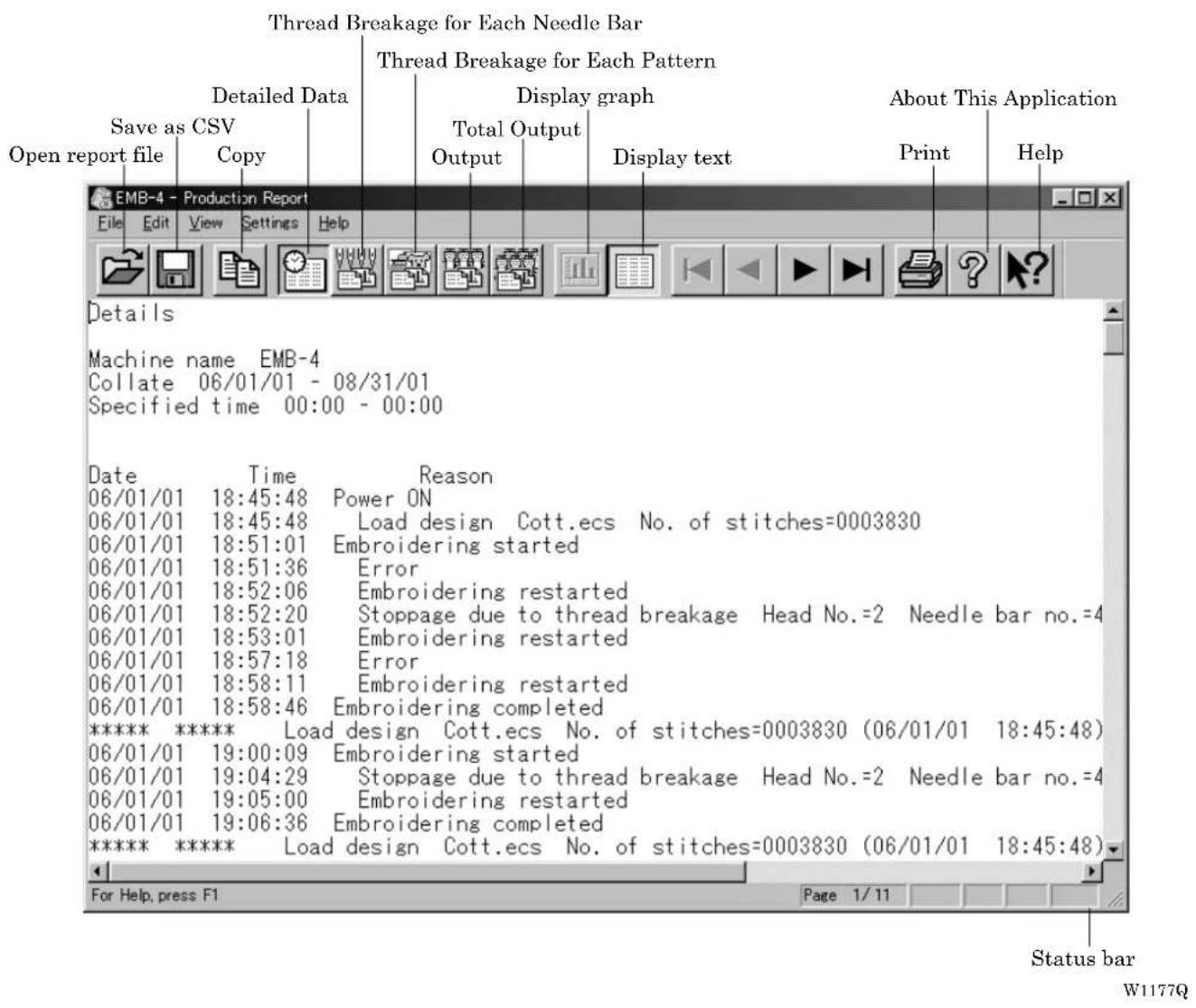
Displaying Report
Displays the machine operation status in the form of report.
■The following reports can be displayed:
| Details Displays detail data while the machine is in operation. | |
| Thread Breakage information on Needle Bar | Displays the thread breakage information for each machine. |
| Thread Breakage information in Pattern | Displays the thread breakage information for each pattern. |
| Output information Displays production output or efficiency of the selected machine. | |
| Total output information Displays production output or efficiency of multiple machines. | |
■ Items to be displayed in each report can be set. For details, refer to "Setting Display Items" (→ page 8-12).
-
Select the desired report from View menu or on the tool bar.
-
Select [Open] from File menu or click

- Select the applicable machine.

-
Click [OK].
-
Specify the period to read.
For more information, refer to "General" in "Setting Display Items" on page 8-12.
- Click [OK].
The report appears.
Display Example of Details
Displays the machine information chronologically that are collected within the specified period.
The following information is indicated under the "Reason" column:
| Display Contents | |
| Power ON | The machine power was turned on.If the computer is turned on after the machine power has been on,it shows the time when the computer recognized the machine. |
| Power OFF | The machine power was turned off.If the computer is turned off before the machine power, it showsthe time when the computer program quit. |
| Load design (*) | The name of the loaded pattern and the number of stitches areindicated. This is also recorded when embroidering was startedafter the power was turned off and back on. |
| Embroidering started Embroidering was started. | |
| Embroidering completed Embroidering was completed. | |
| Embroidering canceled Embroidering was canceled.The information on the pattern is deleted from the record. | |
| Color change (*) | The needle bar number and the number of stitches after colorchange are indicated. |
| Suspended (*) The machine operation was suspended by the operator. | |
| Stoppage due to thread breakage (*) A thread breakage occurred. The head number, the needle barnumber and the speed range are indicated. | |
| Error (*) The machine was stopped due to an error. | |
| Embroidering restarted (*) | Embroidering was restarted after a suspension, a threadbreakage, or an error. |
The items marked with "*" can be shown or hidden on the "Setting items to be displayed" screen.

W1177Q
Display Example of Thread Breakage Information on Needle Bar
Displays the information on thread breakage occurrences with head numbers and needle bar numbers. Three needle bars with frequent thread breakage are indicated.
Display Contents
| No. of times thread is trimmed (*) Number of thread breakage occurrences per needle bar | |
| No. of stitches (*) Number of stitches embroidered with the needle bar during the specified period | |
| Thread breakage rate (*) Thread breakage rate per 10,000 stitches (10000 x No. of times thread is trimmed) /No. of stitches | |
| Total (*) Total for all the heads or all the needle bars | |
| Needle bar with frequent thread breakage occurrence (*) | Three needle bars that have thread breakage frequently, in the decreasing order of frequency |
The items marked with "*" can be shown or hidden on the "Setting items to be displayed" screen.
Display in text
| Thread Breakage Information on Needle Bar | |||||||||
| Machine name: EMB-4 Collate 06/01/01 - 08/01/01 Specified time 00:00 - 00:00 | |||||||||
| Head No. | Needle bar no. | 12 | 11 | 10 | 9 | 0 | 7 | 6 | 5 |
| 1 | No. of times thread breakage occurs No. of stitches Thread breakage rate | 3 403192 0.07 | 7 170005 0.40 | 12 279352 0.60 | 4 255060 0.31 | 2 65008 0.30 | 2 49477 0.41 | 3 245548 0.12 | 24 51576 0.46 |
| 2 | No. of times thread breakage occurs No. of stitches Thread breakage rate | 5 403998 0.11 | 0 171310 0.08 | 2 287265 0.06 | 6 125988 0.47 | 3 65825 0.45 | 3 56008 0.51 | 3 245548 0.12 | 30 521221 0.57 |
| 3 | No. of times thread breakage occurs No. of stitches Thread breakage rate | 8 403195 0.01 | 6 170227 0.34 | 1 279413 0.03 | 1 125496 0.67 | 2 45496 0.30 | 2 56008 0.31 | 0 244191 0.90 | 15 533008 0.29 |
| 4 | No. of times thread breakage occurs No. of stitches Thread breakage rate | 4 497658 0.02 | 3 173334 0.05 | 4 287265 0.13 | 3 127719 0.23 | 5 78221 0.28 | 5 57250 0.63 | 3 245548 0.34 | 4 814204 0.43 |
| Total | No. of times thread breakage occurs No. of stitches Thread breakage rate | 9 1613693 0.05 | 14 689736 0.29 | 24 1315335 0.21 | 14 594293 0.27 | 9 287351 0.33 | 9 218743 0.38 | 7 988829 0.87 | 82 286210 0.44 |
1179Q
Display in graph
The number of thread breakage for each head is displayed with the graph by needle bar.

bar
Thread breakage times (EMB-4) | Head No. | Needle No. 1 | Needle No. 2 | Needle No. 3 | Needle No. 5 | Needle No. 6 | Needle No. 7 | Needle No. 8 | Needle No. 9 | Needle No. 10 | Needle No. 11 | Needle No. 12 | |---|---|---|---|---|---|---|---|---|---|---|---| | No.1 | 2 | 5 | 3 | 2 | 2 | 24 | 17 | 7 | 3 | 3 | 3 | | No.2 | 3 | 3 | 3 | 2 | 2 | 30 | 2 | 6 | 6 | 12 | 1 | | No.3 | 1 | 1 | 1 | 1 | 1 | 15 | 6 | 6 | 6 | 12 | 6 | | No.4 | 1 | 1 | 1 | 1 | 1 | 23 | 7 | 4 | 4 | 4 | 1 |1180Q
Click tab to display the thread breakage rate with the graph.
Display Example of Thread breakage Information in Pattern
Displays thread breakage information for each pattern.
Display Contents
n th The pattern was embroidered for the "n"th time.
Pattern name Name of the pattern that was embroidered
Head No. (*) Head number where a thread breakage occurred
Needle bar no. (*) Needle bar number where a thread breakage occurred
n th stitch (*) The ordinal number of the stitch when a thread breakage occurred
Speed range (*) Speed range that was effective when a thread breakage occurred
The items marked with "*" can be shown or hidden on the "Setting items to be displayed" screen.
Display in text

W1181Q
Display in graph
The number of thread breakage for each pattern is displayed with the graph.

bar
Thread breakout times (EMD-4) | Pattern name | Thread breakage time (EMD-4) | |---|---| | Cott.oo | 10 | | GCamino 5 core charges.oo | 30 | | Valdi.oo | 15 | | KNOCLAS ECS | 25 | | KNOCLAL.oo | 15 | | OOPd.oo | 15 | | belihid.oo | 5 | | Granclap.oo | 2 | | Sondro.oo | 35 | | gsk._led.oo | 15 | | Sordhurt.oo | 25 | | Skital.oo | 5 | | Sous.oo | 2 | | Demi.oo | 3 | | Stredpol.oo | 5 | | Hilar.oo | 15 | | Michael.oo | 15 | | Michael.2.oo | 7 | | Fowlerz.2.oo | 15 | | Pilkoy.oo | 3 | The chart displays the frequency of thread breaks for each pattern name.W1182Q
Click tab to display other patterns with the graph.
Display Example of Output Information
Displays the production information that are collected during the specified period.
| Display Contents | |
| Total electricity supply time | Total time when the machine was energized within the specified period(**) |
| Total embroidering time Total time when the machine embroidered within the specified period | |
| Total actual embroidering time Total actual time when the machine embroidered within the specified period | |
| Excluded time Total time of intermission and maintenance for the number of days in the specified period | |
| Electricity supply efficiency Electricity supply efficiency by calculating below:(Total electricity supply time - excluded time) / total electricity supply time | |
| Embroidering efficiency period Ratio of the actual embroidering time to the total embroidering timeTotal actual embroidering time / total embroidering time | |
| Number The pattern embroidered during the specified period is numbered. | |
| Pattern name Name of the pattern | |
| No. of stitches in pattern Number of stitches in the pattern | |
| Total stitches (*) | Total number of stitches by repeating embroideringNo. of stitches in pattern X No. of times embroidered |
| No. of colors in pattern (*) Number of colors in the pattern | |
| No. of times embroidered (*) Number of embroidering repeated | |
| No. of workpieces embroidered (*) Number of finished sheets by one embroidering cycle | |
| Total no. of heads which are stopped | Total number of the heads at rest for one embroidering cycle |
| Embroidering time (*) | Time from embroidering start to the end for the pattern |
| Actual embroidering time (*) | Embroidering time from which the time for interruption, stop due to thread breakage, and stop due to error is excluded |
| Average embroidering speed | Average embroidering speed in the actual embroidering time (the number of stitches per minute)Total stitches/actual embroidering time |
| Efficiency 1 (*) | Ratio of the actual embroidering time to the embroidering time for the pattern with time for interruption excludedActual embroidering time/(embroidering time-time for interruption) |
| Efficiency 2 (*) | Ratio of the actual embroidering time to the embroidering timeActual embroidering time / embroidering time |
| Time stopped (*) | Total of stop time during embroidering |
| Reason for stoppage (*) | Reasons for stoppage are indicated. Refer to the next page. |
The items marked with "*" can be shown or hidden on the "Setting items to be displayed" screen. **) Electricity supply time is totaled per one day.
Details of reason for stoppage
Interrupted Frequency and total time stopped by the operator
Stoppage due to thread breakage Frequency and total time stopped by thread breakage
Error Frequency and total time stopped by errors
Display in text
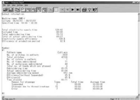
W1183Q
Display in graph
The output information is displayed with the graph.
Displayed here is the screen of embroidering efficiency.

bar
Quantity of production output (EMB-4) | Pattern name | Quantity of production output | |---|---| | Cott.eco | 60 | | UCAdion 5 color changes.eco | 145 | | Vald.eco | 25 | | KINGCLAS_ECS | 60 | | KENOCLAI.eco | 145 | | CI004.eco | 20 | | belliniu.eco | 20 | | Vald Cap jcb2001guava.eco | 20 | | Orankap.eco | 60 | | family.eco | 0 | | Less.eco | 0 | | Sorebro.eco | 25 | | Capaillre.eco | 0 | | gjk_test.eco | 80 | | Sorbhart.eco | 20 | | Shield.eco | 15 | | Souz.eco | 15 | | Fenni.eco | 15 | | Master.eco | 5 | | Roben.eco | 5 |W1184Q
Click tab to display the total embroidering time, etc, with the graph.
Display Example of Total Output Information
Displays the output information per pattern on multiple machines that are selected.
| Display Contents | |
| Number The pattern embroidered during the specified period is numbered. | |
| Pattern name Name of the pattern | |
| No. of stitches in pattern Number of stitches in the pattern | |
| Total stitches (*) | Total number of stitches by repeating embroideringNo. of stitches in pattern X No. of times embroidered |
| No. of colors in pattern (*) Number of colors in the pattern | |
| No. of times embroidered (*) Number of embroidering repeated | |
| No. of workpieces embroidered (*) Number of finished sheets by one embroidering cycle | |
| Total no. of heads which are stopped Total number of the heads at rest for one embroidering cycle | |
| Embroidering time (*) Time from embroidering start to the end for the pattern | |
| Actual embroidering time (*) | Actual embroidering time excluding the stop time by thread breakage, suspension and errors from the embroidering time |
| Actual embroidering speed (*) | Average embroidering speed in the actual embroidering time (the number of stitches per minute)Total stitches/actual embroidering time |
| Efficiency 1 (*) | Ratio of the actual embroidering time to the embroidering time for the pattern with time for interruption excludedActual embroidering time/(embroidering time-time for interruption) |
| Efficiency 2 (*) | Ratio of the actual embroidering time to the embroidering timeActual embroidering time / embroidering time |
| Time stopped (*) Total of stop time during embroidering | |
| Reason for stoppage (*) | Reasons for stoppage are indicated. Refer to page 8-9. |
The items marked with "*" can be shown or hidden on the "Setting items to be displayed" screen.
Display in text

W1185Q
Display in graph
The total output information is displayed with the graph.
Displayed here is the screen of the number of embroidered cloths.

bar
Quantity of production output | Pattern name | Quantity of production output | |---|---| | Ceft eco | 45 | | Pramino-5 color changes eco | 155 | | Valad eco | 25 | | KID-CLAS-ECs | 48 | | KID-CLAS-ECs | 150 | | Otoa eco | 22 | | Bellinal eco | 20 | | Lat Cap joly-200 gamma eco | 25 | | Granap eco | 48 | | family eco | 0 | | Leau eco | 0 | | Sorreiro eco | 25 | | Capetro eco | 70 | | glic. tool eco | 18 | | Soralirt eco | 15 | | Shellid eco | 12 | | Motor eco | 10 | | Damir eco | 8 | | Master eco | 6 | | Roem eco | 98 | | Sweeped eco | 18 | | Bitar eco | 10 | | Machard eco | 8 | | Klubart-2 eco | 6 | | Willowlit eco | 6 | | Powwar-2 eco | 12 | | Friday eco | 18 | | Biwood eco | 15 | | Snowwatch-3 eco | 6 | | Starwatch-3 eco | 28 |W1186Q
Click tab to display the total embroidering time, etc, with the graph.
Setting Display Items
Sets display items for each production report.
■The following tab windows can be set:
| General Items related to the overall display of the output report. | |
| Details Items related to detail data. | |
| Thread Breakage information on Needle Bar | Items related to thread breakage for each needle bar. |
| Thread Breakage information in Pattern | Items related to thread breakage for each pattern. |
| Output information Items related to output information. | |
| Total output information Item related to total output information. | |
| Recess time setting Items not included in the efficiency calculation for output information and total output information. | |
- Select [Items to be displayed] from Settings menu.
- "Setting items to be displayed" screen appears.
Click the tab on the screen and the tab window for the items appears.

W1187Q
General

W1187Q
■Collate
Selects the data collection period. If month, week or day is selected, set the end date or end hour.
■Storage
Selects the data save period.
Details

W1188Q
■Main items to be displayed
Displays each event and the time.
Load design Transfer time of embroidery data
Color change Time of color change
Stoppage due to thread breakage Time of thread breakage
Restart Time of resuming embroidering after suspension
Stop after pressing button Time when the emergency stop button was pressed
Suspended Error Time when an error has occurred
■Sub items to be displayed
Displays the following for each item in main display items.
Head no. Head number
Needle no. Needle number
No. of stitches Number of stitches
Speed range Speed range
Thread Breakage Information on Needle Bar

W1189Q
■Main items to be displayed
No. of thread breakage occurrences Number that thread breakage has occurred
No. of stitches Number of stitches used in embroidery
Thread breakage rate Rate of thread breakage for 10,000 stitches
■Sub items to be displayed
Displays the following for each item in main display items.
Total Total of the item for each head and each needle
Needle Bar with frequent thread breakage occurrences Data of three needles that have caused thread breakage most frequently
Thread Breakage Information in Pattern

W1190Q
Head no. where thread breakage occurred Head number that has caused thread breakage
Needle bar no. where thread breakage occurred Needle number that has caused thread breakage
No. of stitches until thread breakage Number of stitches until thread breakage has occurred
Speed range Speed range when thread breakage has occurred
Output Information
Time is calculated to the unit of second, but the display unit is in minute. This may result in minor differences.

W1191Q
■Items to be displayed
| Total stitches The total number of embroidery stitches from start to end | |
| No. of times embroidered Number of embroidering | |
| Embroidering time The total time from start to end spent for embroidery | |
| Actual embroidering time Time spent for embroidering | |
| Time stopped Time not spent for embroidering | |
| Embroidering efficiency Actual embroidery time/ (Embroidering time-Interrupted)Actual embroidery time/Embroidering time (in %) | |
| Reason for stoppage Event that caused a stop | |
| No. of colors in pattern Number of colors in pattern | |
| No. of workpieces embroidered Number of sheets embroidered. | |
| Average embroidering speed | Number of total stitches/Actual embroidery time(number of stitches for 1 minute in embroidering) |
■Reason for stoppage
Items for selection appear when [Reason for Stoppage] is clicked in the "Items to be displayed" column.
The display shows for three cases: emergency button stop, thread breakage, and error stop.
| Times | Number of stops |
| Total time | Total stop time |
| Average time | Average stop time per occurrence (in seconds) |
Total Output Information
Time is calculated to the unit of second, but the display unit is in minute. This may result in minor differences.

W1192Q
■Items to be displayed
| Total stitches The total number of embroidery stitches from start to end | |
| No. of times embroidered Number of embroidering | |
| Embroidering time The total time from start to end spent for embroidery | |
| Actual embroidering time Time spent for embroidering | |
| Time stopped Time not spent for embroidering | |
| Embroidering efficiency Actual embroidery time/ (Embroidering time-Interrupted)Actual embroidery time/Embroidering time (in %) | |
| Reason for stoppage Event that caused a stop | |
| No. of colors in pattern Number of colors in pattern | |
| No. of workpieces embroidered | Number of sheets embroidered. |
| Average embroidering speed | Number of total stitches/Actual embroidery time(number of stitches for 1 minute in embroidering) |
■Reason for stoppage
Items for selection appear when [Reason for Stoppage] is clicked in the "Items to be displayed" column.
The display shows for three cases: emergency button stop, thread breakage, and error stop.
| Times | Number of stops |
| Total time | Total stop time |
| Average time | Average stop time per occurrence (in seconds) |
■Target machine
Click and select the machine for calculation. To cancel the selection, click again.
Recess Time Setting
Sets the time not to be included in the calculation. This time is displayed on the "Output" report as "Time Excluded".
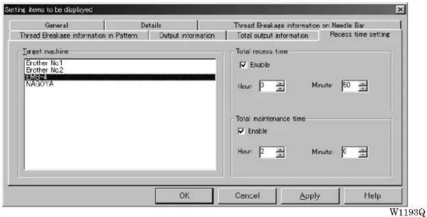
■Target machine
Click and select the applicable machine for calculation.
■Total recess time
Set the time not to be included in the day-to-day calculation during the designated period.
■Total maintenance time
Set the time not to be included in the calculation throughout the period.
Save As CSV...
Converts the production report data to CSV format that can be read in spreadsheet software.
- Select [Save As CSV] from File menu or click

-
The file name "Untitled.csv" automatically appears. To change the name, change "Untitled".
-
Select the directory to be saved and click [Save].

W1194Q
■What is CSV format?
CSV (Comma Separated Value format) means a type of file formats used for PC. Data in each item is divided by commas and recorded as a text file. This format is mainly used for a spreadsheet software or data base software. The extension is "csv".
Printing Production Report
Prints the production report from a printer.
Page Setup
Printing method is set as required.
1. Select [Page setup] from the File menu.
Setting screen is displayed.

1. Select [Print] from File menu or click
![BROTHER BE-1204C-BC - Select [Print] from File menu or click - 1](/content/2026/05/1004755/images/afc18156da43cd0f8f7bf5fcd4adec60c49f58a04ea4c97d0685b83a4e1e4418.jpg)
Set the number of sheets and click [OK].
Copying Report Data
Copies the selected area as text data. This allows use of the production report on other word processing software.
- Select [Select All] from Edit menu, or drag and select the area to be copied.

W1196Q
When dragging for selection

W1197Q
When selecting [Select All]
-
Select [Copy] from Edit menu or click .
-
The area is copied as text data. Start a word processing software and select [Paste] from Edit menu.
Copied data is saved until another data is copied or cut.
Chapter 9 Maintenance
CAUTION

Turn off the power switch before starting maintenance.
Failure to do so may start the machine unintentionally through an accidental activation of the START switch, resulting in bodily injuries.

Be sure to wear protective goggles and gloves when handling the lubricating oil or grease, so that no oil or grease gets into your eyes or onto your skin, otherwise inflammation can result.
Furthermore, do not drink the oil or grease under any circumstances, as they can cause vomiting and diarrhoea.
Keep the oil out of the reach of children.
- Keep the machine clean at all times to prevent machine trouble.
- Remove dirt with a soft, dry cloth. If necessary, clean with the detergent-soaked cloth, then wipe off the detergent with a cloth dampened with (hot) water.
- Never use benzene or thinner for cleaning the machine.
1. Cleaning
1-1 Cleaning and Lubrication of Rotary Hook
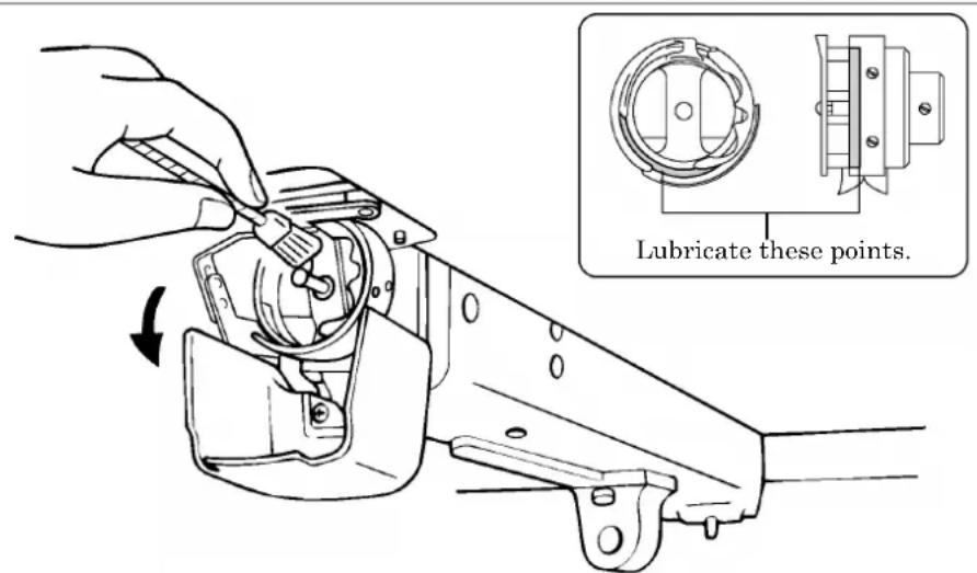
W1288Q
- Clean rotary hooks daily using the brush provided at the time of lubrication. If a rotary hook is too dirty, cleaning with a compressor (compressed air) is recommended.
- In case of thread breakage errors or noises of the rotary hook, one drop lubricate the race of the rotary hook in every 3 or 4 hours operation.
- Use the dropper provided to supply oil. Use Brother's specified oil (Nippon Oil, Embroidery Lube 10N; VG10).
* If this type of lubricating oil is difficult to obtain, the recommended oil to use is
- Supply a proper amount of oil. Any excess may stain fabrics, etc.
1-2 Cleaning of Needle Plate

natural_image
Technical line drawing of a mechanical component with an arrow indicating assembly or adjustment (no text or symbols present)Remove broken threads from this section.
W1290Q
Broken threads left around the movable or fixed knives or the lower thread holding plate may result in thread trimming failure or parts damage. Clean them once a month.
2. Oiling
Supply oil to the following places at regular intervals.
- When oiling, be sure to supply Brother's specified oil (Nippon Oil, Embroidery Lube 10N; VG10) using the dropper.
* If this type of lubricating oil is difficult to obtain, the recommended oil to use is
- Excessive oiling may cause the material to be stained.
- Be sure to wipe off excessive oils with waste cloth etc.
2-1 Head
■ Supply one or two drops of oil to each needle bar from the oil supply hole of the lower cover daily.
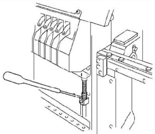
natural_image
Technical line drawing of a mechanical assembly with no visible text or symbolsW1221Q
■Lubricate the felt on the top surface of the head once a week.

W1291Q
2-2 Lower shaft
■Lubricate the lower shaft bush R through the hole once a month.

natural_image
Line drawing of a mechanical component with an arrow pointing to a specific part (no text or symbols present)W1292Q
■Lubricate the lower shaft bush F every 3 months.
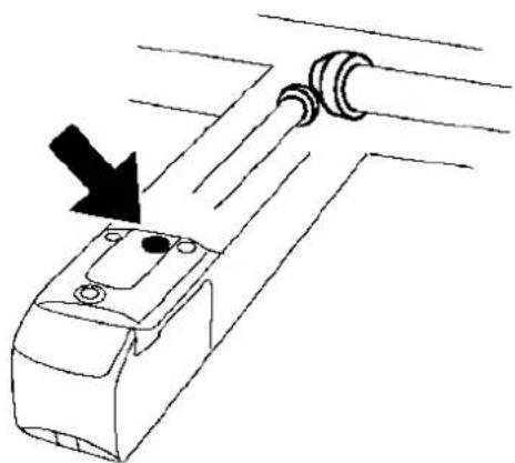
natural_image
Line drawing of a mechanical component with a black arrow pointing to a shaft (no text or symbols)W1293Q
3. Greasing
Supply grease to the following places at regular intervals.
- When greasing, be sure to use the grease tank EM-30L (white) provided with the machine.
- For overhauling, contact your distributor or refer it to trained experts.
3-1 Cam grooves
■Supply grease to cam grooves (two positions) once a month.
- Remove the head cover.
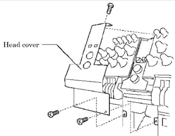
W1294Q
- Move the needle bar case to the needle bar No.12 position.
- Unscrew the lower flat screw [2] fixing the head front cover L [1], and loosen the upper fixing screw [3]. Remove the head front cover L [1].
![[4] [5] [3] [1] [2] [2]](/content/2026/05/1004755/images/259e8ea64d3752512fc2215e914b5b810e89e186accd09947fb24230dc7eb7ee.jpg)
W1295Q
-
Unscrew the two adjusting bolts [4] and detach the jump part stepping motor [5].
-
Grease all the cam grooves of the work clamp cam.
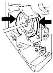
natural_image
Mechanical assembly diagram showing a wheel and mechanical components (no text or labels)W1297Q
-
Attach the jump part stepping motor [5] and tentatively tighten the adjusting bolt [4].
-
Adjust the position of the bolt [4] so that the jump part [6] touches the roller [7] of the jump lever assembly, then fully tighten the bolt [4].
Adjust the roller [7] not to push the jump part [6] but just touches it.
![[6] [7]](/content/2026/05/1004755/images/72921afc85074292ccd314b6f88b95cdeb9a8950601a477a63e3b011880d9bea.jpg)
W1298Q
- Attach the head cover front L [1].
Apply seal adhesive (equivalent of Three Bond 1215) to the attaching face of the head before attaching the cover.
-
Move the needle bar case to the needle bar No.1 position.
-
Unscrew the 2 fixing screws [8] fixing the head front cover R [9], and remove the head front cover R [9].
![[9] [8] [10]](/content/2026/05/1004755/images/96666555591e442a6887d473d0a2aee6b243c57b791d7990dbd33eec8af0da0b.jpg)
W1299Q
-
Grease all the cam grooves of the thread take-up driving cam [10].
-
Attach the head front cover R [9].
Apply seal adhesive (equivalent of Three Bond 1215) to the attaching face of the head before attaching the cover.
3-2 Lower gear
■Supply grease to the lower gear every three months.
- Unscrew the 4 flat head screws fixing the bed cover B, and remove the bed cover B.
- Grease the lower gear.

natural_image
Diagram of a car with a directional arrow indicating motion or force (no text or symbols present)W1301Q
- Attach the bed cover B.
3-3 Driving shaft
■Supply grease to the driving shaft every three months.
- Unscrew four screws fixing the table cover L, and remove the table cover L.
- Grease the intermediate gear.
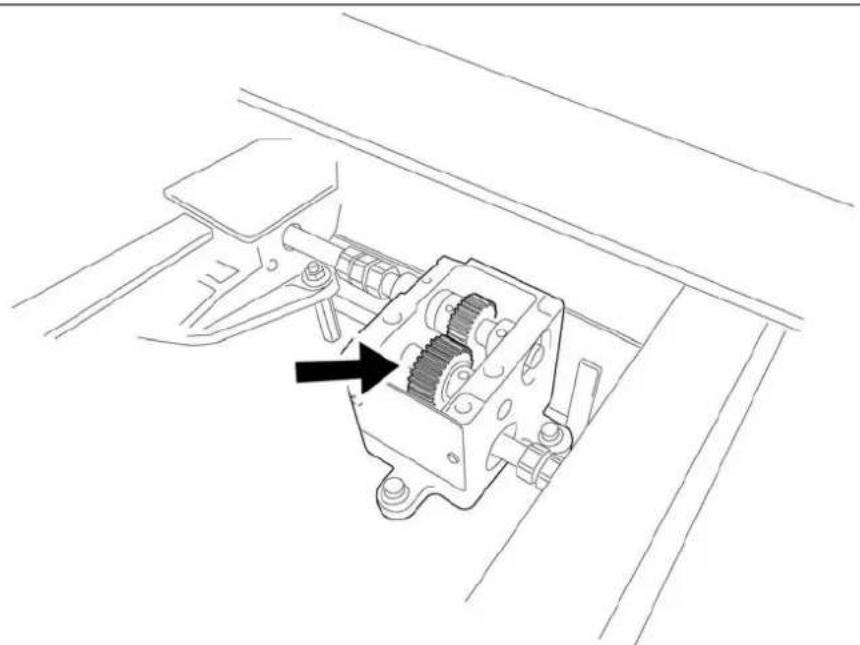
natural_image
Technical line drawing of a mechanical assembly with gears and levers (no text or symbols)W1397Q
- Attach the table cover L.
3-4 Needle bar flip-up mechanism
■Supply grease to the needle bar flip-up mechanism every three months.
- Unscrew three screws fixing the head cover R, and remove the head cover R.
- Grease all the cam grooves and two gears.
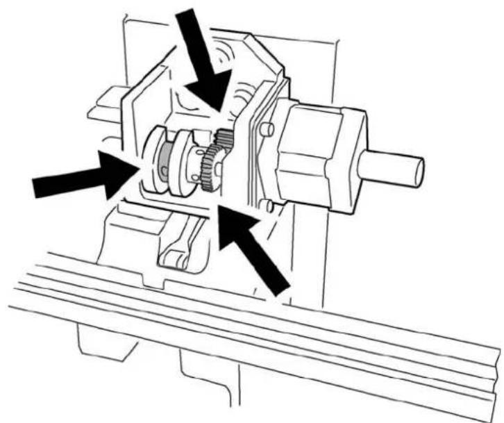
natural_image
Technical line drawing of a mechanical assembly with gears and shafts (no text or symbols)W1398Q
- Attach the head cover R.
3-5 Feed Guide Section
■ Check the X-feed linear guides (2 positions) and the Y-feed linear guides (one each on the right and left, and one point on bed No. 3).
![[1] [2] [3] [8] [9] [5] [6] [4] [7] [10] [11] W1302Q W1303Q](/content/2026/05/1004755/images/1a035c2b77b78107f09e820231e52b4e54ed3f03b6c536b53d4c1fef1152131e.jpg)
Procedure
- Unscrew the screw [1] and remove the X-feed covers R [2] and L [3].
For four head models, just remove the X-feed cover R [2] only. - Unscrew the screw [4] and remove the table covers R [5] and L [6].
- Unscrew the screw [7] and remove the Y-feed covers R front [8], R rear [9], L front [10] and L rear [11].
- Grease the X-feed linear guide parts (2 positions) and Y-feed linear guide parts (2 positions), and slide those parts to spread the grease.
- Assemble all the components in the reverse order.
Chapter 10 Adjustment

CAUTION

Turn off the power switch and pull out the plug before starting adjustment. Failure to do so may start the machine unintentionally through an accidental activation of the START switch, resulting in bodily injuries.
- Adjustment

If adjustment should be made while the power switch is turned on, pay special attention to your safety.

Maintenance and inspection of the machine should be conducted only by trained engineers.
1. Adjusting Needle Bar Height

natural_image
Pure technical line drawing of a mechanical part without any text, numbers, or symbolsW1304Q W1305Q
![[5] [4] [6] [2] [3] 11.3mm](/content/2026/05/1004755/images/3f4d11e4d34317e1098b0987eda67d0686a7e60d213f74e48a570e5e0953ca9d.jpg)

![[5] [4] [6] Tighten the bolt [6] so that the clearance can be even. [7] Do not hit this section. [7]](/content/2026/05/1004755/images/9ee203697b498e0d3d1882f92370326343d89b19fb87b30b25825d1fba1c4595.jpg)
W1306Q W1296Q W1307Q
- Put the attached T-shaped hexagonal wrench (4 mm) into the hole [1] on the left side of the machine body, and adjust the arrow plate to align with 180 degrees (N.D mark) to move the needle bar to the lowest point.
- Loosen Needle bar guide bracket set screw [2] and the bolt [6] of the top dead center stopper [4] when the needle tip is positioned 11.3 mm above the center of the rotary hook shaft. Adjust the position of the needle bar thread guide so that the set screw [3] on it is turned to the right by 25 \~ 30°. Tighten Needle bar guide bracket set screw [2] securely.
When tightening the needle bar clamp set screw [2], the hole in the needle bar guide should face the front. - Set the needle bar at the highest position (where the arrow plate and the "N.U." mark are aligned). Lightly press the top dead center stopper [4] toward the cushion rubber [5], and tighten Socket head bolt for top dead center stopper [6] while pressing down the needle bar clamp so that it faces the front. (Tightening torque: 0.78 N.m)
- Make sure that the top dead center stopper does not hit the needle bar guide rail [7] at this time.
- When tightening the upper dead point stopper bolt [6], insert the longer side of the attached wrench into the bolt and tighten it by using the shorter side.
Excessive tightening may make the needle bar movement sluggish.
■When using the bottom dead center gauge

W1307Q
-
Put the attached T-shaped hexagonal wrench (4 mm) into the hole [1] on the left side of the machine body, and adjust the arrow plate to align with 180 degrees (N.D mark) to move the needle bar to the lowest point.
-
Insert the bottom dead center gauge [2] into the rotary hook [3].
-
Loosen the screw [5] of the needle bar clamp [4] and Socket head bolt for top dead center stopper [8], then move the needle bar up and down until the needle tip touches the gauge [2] lightly.
-
The needle point should touch the gauge at a place other than the cutting section.
-
The bottom dead center gauge should be set in or removed from the rotary hook with its cutting section facing upward.
-
Tighten the screw [5] of the needle bar clamp [4] securely.
-
Set the needle bar at the highest position (where the arrow plate and the "N.U." mark are aligned). Lightly press the top dead center stopper [6] toward the cushion rubber [7], and tighten Socket head bolt for top dead center stopper [8] while pressing down the needle bar clamp so that it faces the front. (Tightening torque: 0.78 N.m)
-
Make sure that the top dead center stopper [6] does not hit the needle bar guide rail [9] at this time.
- When tightening the upper dead point stopper bolt [8], insert the longer side of the attached wrench into the bolt and tighten it by using the shorter side.
Excessive tightening may make the needle bar movement sluggish.
2. Attachment and Adjustment of Rotary Hook
![12 1 1c u s f c b f s 2 [1]](/content/2026/05/1004755/images/93f232135f3acd4ba76520ce93da5d698eae55419a12499ee814473a441f423a.jpg)
W1309Q W1310Q
![[2] [3] [6]](/content/2026/05/1004755/images/d5843fccc2a15e982985b8d071f5479adea8c5171f31d1ea5dfc94796148f77b.jpg)
![1.8 mm 1.7 mm [4] [5]](/content/2026/05/1004755/images/ea3bfdc0bdcd58e858d5ecbcda401075266eb0a0900002481feaa700a3cdfecf.jpg)
W1311Q W1314Q

![Lower shaft [6] Cutting](/content/2026/05/1004755/images/e80da4fc0be75091b59f71c76193ef06f5a98d1696ae556f0c4ee0ff7f40d340.jpg)
section

W1312Q W1313Q
- Turn the power switch off.
- Select the needle bar No. 1 [1].
- Remove two flat screws [2] and dismount the needle plate [3].
- Adjust so that the needle [4] and the point of rotary hook [5] should meet at the position (where the arrow plate aligns with N.H mark (200°)) higher by 1.7 mm than the needle bar lowest point (180°). Perform this after the height adjustment of the needle bar.
- Turn the rotary hook manually until the point of rotary hook [5] turns up.
-
Loosen the screw [6] of the rotary hook cutting section and adjust the clearance between the needle and the rotary hook to be within 0.1 to 0.3mm . Confirm that the height of the needle bar is 1.8mm then.
-
Tentatively tighten the screw [6].
-
Check with needle bars of No. 2 to No. 12 if the clearance between each needle and the rotary hook is within 0.1 to 0.3 mm.
If there are any needles with clearances out of the range above, adjust them again to get proper clearances.
- Fully tighten the screw [6].
3. Adjustment of Presser Foot Height

W1314Q W1315Q
![[2] [1] material](/content/2026/05/1004755/images/8cffa86cc7fd5539c7a6caf13f9e61f7a6f8d458de666928a31846e909fff993.jpg)
- Turn the power switch off.
- Select the needle bar No. 1.
- Loosen the screw [2] of the presser foot [1], and adjust the presser foot [1] until it comes above the cloth top surface when it is at the alignment position (where the arrow plate and the "N.H" mark (200°) are aligned).
When the presser feet have been adjusted in height, check that each needle lowers to the center of the presser foot hole.
- Adjust the arrow plate to align with 100 degrees, and then change colors.
Adjust the needle bar No.2 - No.12 similarly.
4. Thread Wiper Adjustment
![[1] [2] [3] [4] [5] Back and forth Up and down W1325Q](/content/2026/05/1004755/images/77b797d33695b83ef503a733e6be802fcd0b75c88750c2a9790f0af914efe529.jpg)
-
Move wiper lever assy [1] in the direction of the arrow with your finger. If there is a difference in motion of upper thread hook [2] as to needle bars No.1 and No.2, loosen four screws [3] and move thread nipper assy [4] in the direction of the arrow for adjustment. At adjustment, make it sure that no interference will occur when pressure foot [5] is recessed to the feed position (100°).
-
After the above steps are complete, move thread hook [2] to check its smooth movement.
Chapter 11 Error code list
| Code B | Error Measures | |
| E-00 N | No error occurs. | This is not usually displayed. |
| E-01 | Either motor of main shaft, X- or Y-axis, or lower shaft has locked. | |
| E-02 | Overtravel occurs during home position detecting movement. | |
| E-03 | The stop switch is pressed during home position detecting movement. | Press the  [8422] turn on the F/B switch on the head to either side to restart the home position detecting movement again. [8422] turn on the F/B switch on the head to either side to restart the home position detecting movement again. |
| E-04 H | Home position detection out of range This is not usually displayed. | |
| E-05 N | Needle stop position error | Adjust the pulley stop position (100 degrees) above the needle and press the STOP or turn on the F/B switch on the head to either side. |
| E-06 N | Needle bar case position error | Adjust the position of needle bar case manually, then press the STOP or turn ON the F/B switch on the head to either side. If the same error occurs again, the color change proper position sensor is faulty. |
| E-07 N | Needle bar case lock | Press the STOP or turn on the F/B switch on the head to either side. If the same error occurs again, the color change mechanism is faulty. |
| E-08 | Stop switch or emergency switch was pressed while the needle bar case is traveling. | This is not usually displayed. |
| E-09 X | -axis home position detection error | Turn the power off and on once. If the same error occurs again, the X-axis mechanism is faulty. |
| E-0A T | Thread breaking error | After passing through the thread, press the STOP or turn on the F/B switch on the head to either side. |
| E-0B S | Stop or emergency stop during sewing This is not usually displayed. | |
| E-0C L | Lower thread broke during embroidering. | After the replacement of the lower thread, press the STOP or turn ON the F/B switch on the head to either side. |
| E-0D | The machine does not return to the home position. | This is not usually displayed. |
| E-0E M | Mending finish | |
| E-0F F | Failed in the reading of needle bar No. | Press the STOP or turn ON the F/B switch on the head to either side. If the same error occurs again, the I/O CPU communication is faulty, or the color change position sensor is faulty. |
| E-10 A | Abort by the beam sensor ON | Press the STOP or turn ON the F/B switch on the head to either side. |
| E-11 | Failed in the reading of X home position sensor | Press the STOP or turn ON the F/B switch on the head to either side. If the same error occurs again, the I/O CPU communication is faulty. |
| E-12 F | Failed in the reading of X home position sensor | Press the STOP or turn ON the F/B switch on the head to either side. If the same error occurs again, the I/O CPU communication is faulty. |
| Code | Error Measures | |
| E-13 | This is displayed in case that the machine had been shut down while the hoop was moving and now is started up in a mode without the home position detection, or in case that the machine is started up in a mode without the home position detection after pressing the CAP SW to change the hoop. | Press theto start the home position moving. |
| E-14 Y | -axis home position error | Turn the power off and on once. If the same error occurs again, the Y-axis mechanism is faulty. |
| E-15 | Stop error during SSP processing (when pressing the stop key while the hoop is moving) | Hoop movement restarts if you pressSTART. |
| E-16 | Needle bar No. of the destination is out of range | Press theSTOP, or turn ON the F/B switch on the head to either side to cancel the error and set up the needle bar setting again. |
| E-17 S | speed range is out of range This is not usually displayed. | |
| E-18 X | axis stepping motor connector error | Turn the power off and on once after checking to see that the connector of the X-axis stepping motor is properly connected. |
| E-1A Destination coordinates error | This is not usually displayed. | |
| E-1B | The machine has reached the mending stop position. | |
| E-1C T | the machine stops during mask tracing. | Tracing is cancelled if theSTOPkey is pressed when the machine is stopped during mask tracing. Press thekey to continue tracing. |
| E-1D | The machine stops while the needle is moving between patterns during repeat sewing. | This is displayed when the stop switch is pressed while the hoop is moving. Press theto move the hoop again. (It is necessary to press theagain to start sewing.) |
| Errors E-1C and E-1D are not displayed due to mechanical problems. | ||
| E-1E | When the power is turned on, bed can not be retracted. | This is not displayed in this model. |
| E-1F | Presser foot down error while searching for home position just after the power is turned on. | |
| E-21 Hoop overhang (+X) | Pattern or the needle position is out of the embroidering area. Reset the embroidering area with the PC or move the hoop to the sewable position. | |
| E-22 Hoop overhang (+Y) | ||
| E-23 Hoop overhang (+X, +Y) | ||
| E-24 Hoop overhang (-X) | ||
| E-25 Hoop overhang (+X, -X) | ||
| E-26 Hoop overhang (-X, +Y) | ||
| E-27 Hoop overhang (+X, -X, +Y) | Pattern or the needle position is out of the embroidering area. Reset the embroidering area with the PC or move the hoop to the sewable position. | |
| E-28 Hoop overhang (-Y) | ||
| E-29 Hoop overhang (+X, -Y) | ||
| E-2A Hoop overhang (+Y, -Y) | Pattern or the needle position is out of the embroidering area. Reset the embroidering area on the panel or move the hoop to the sewable position. | |
| E-2B Hoop overhang (+X, +Y, -Y) | ||
| E-2C Hoop overhang (-X, -Y) | ||
| E-2D Hoop overhang (+X, -X, -Y) | ||
| E-2E Hoop overhang (-X, +Y, -Y) | ||
| E-2F Hoop overhang (+X, -X, +Y, -Y) | ||
| E-31 Needle overhang (+X) | ||
| E-32 Needle overhang (+Y) | ||
| E-33 Needle overhang (+X, +Y) | ||
| E-34 Needle overhang (-X) | ||
| E-36 | Needle overhang (-X, +Y) | Pattern or the needle position is out of the embroidering area. Reset the embroidering area on the panel or move the hoop to the sewable position. |
| E-38 | Needle overhang (-Y) | |
| E-39 | Needle overhang (+X, -Y) | |
| E-3C | Needle overhang (-X, -Y) | |
| E-40 | The status of presser foot is issued as an alarm when every second machine is used. | This is not usually displayed. |
| E-41 | Invalid start-up error | |
| E-42 | XY movement error | Press the STOP or turn on the F/B switch on the head to either side. If this error occurs frequently, check if the tension of the pulley belt is proper. |
| E-43 | I/F CPU failed to read EEPROM data | Turn the power off and on once. If the same error occurs again, the main PC is faulty. |
| E-44 | Failed in the communication with inter-head CPU | Press the STOP or turn ON the F/B switch on the head to either side. If the same error occurs again, the connector of communication cable on the inter-head CPU may be disconnected. |
| E-45 | Failed in the communication with head CPU | Press the STOP or turn ON the F/B switch on the head to either side. If the same error occurs again, the connector of communication cable on the head CPU may be disconnected. |
| E-46 | Failed in the communication with XY CPU | Press the STOP or turn ON the F/B switch on the head to either side. If the same error occurs again, the main PCB is faulty. |
| E-47 | Failed in the communication with I/F CPU | Press the STOP or turn ON the F/B switch on the head to either side. If the same error occurs again, the main PCB is faulty. |
| E-48 | The main shaft rotated the opposite way | Turn OFF the power and check if the sensors of the encoder A and B are connected correctly, not mixed-up each other. If those connections are correct, then check if the pin connections of the main shaft motor connectors are correct. |
| E-49 | Can not identify the machine model | Turn OFF the power, check if the model identification harness is connected properly, and turn ON the power again. |
| E-4A | Failed in the communication with I/O CPU | Press the STOP or turn ON the F/B switch on the head to either side. If the same error occurs again, the connector of communication cable on the I/O PCB may be disconnected. |
| E-A1 | Spindle motor lock | Press the STOP or turn on the F/B switch on the head to either side. If it occurs frequently, the main shaft mechanism is faulty. |
| E-A2 | Main PC board temperature too high | This is not usually displayed. |
| E-A3 | Spindle motor voltage too low | |
| E-A4 | Spindle motor voltage too high | |
| E-A5 | Spindle motor CPU error | |
| E-A6 | Spindle motor CPU communication command error | |
| E-A7 | Spindle motor CPU send/receive error | |
| E-A8 | Spindle stop position signal error | Adjust the pulley stop position (100°) above the needle and press the STOP. If the error occurs frequently, the parts related to the main shaft stop position sensor are faulty. |
| E-A9 | Spindle CPU parameter error | This is not displayed in this model. |
| E-B0 | Lower shaft CPU error | |
| E-B1 | Thread tangle in rotary hook | |
| E-B2 | Hook motor home position error | This is not displayed in this model. |
| E-B3 | Hook motor standby position error | |
| E-B4 | Hook motor motor mode error | |
| E-B5 | Hook motor communication error | |
| E-B6 | Hook motor parameter error | |
| E-B7 | Hook motor overheat error | |
| E-B8 | Hook motor overcurrent error | |
| E-B9 | Thread trimming motor zero point error | Turn the power off and on once. If the same error occurs again, the lower shaft motor is faulty. |
| E-BA | Power supply frequency error | Turn the power off and check the thread trimmer and turn the power on again. If it occurs again, the thread trimmer is faulty. |
| E-BC | No power error | It may usually occur momentarily when turning off the machine. If it occurs when the machine is on, it is a power failure detection error. |
| E-BD | Lower shaft flash memory error | This is not displayed in this model. |
| E-BE | Lower shaft version-up error | |
| E-BB, BF | Lower shaft motor undefined error | |
| E-C1 | Area over during embroidering | |
| E-C2 | Wiper out error | If the wiper is tangled with a thread, remove it. Press the or turn on the F/B switch on the head to either side. |
| E-C3 | Embroidering data buffer empty | Check the connection of the communication cable of the panel. If the cable is connected correctly , press the STOP or turn on the F/B switch on the head to either side. If the cable is disconnected , turn off the power and connect the cable. |
| E-C4 | Presser foot down error | This is not displayed in this model. |
| E-C5 | Measured voltage value could not be received form the lower shaft motor CPU. | |
| E-C6 | Voltage value could not be transferred to the lower shaft motor CPU. | |
| E-C7 | Lower shaft error | |
| E-C8 | Hook motor home position error | |
| E-C9 | Embroidering start error | |
| E-CA | No sewing permission | |
| E-CB | Spindle rotation speed error | Press the STOP or turn on the F/B switch on the head to either side to cancel the error and press the START. If the same error occurs again, there is a possibility that the spindle is overloaded. |
| E-CC | Shuttle thread entanglement automatic reset This is not usually displayed. | |
| E-CD | Speed command can not be received. | Turn the power off and on once. If the same error occurs again, the main PCB is faulty. |
| E-CE | Cylinder bed position error | This is not usually displayed. |
| E-CF | Rated voltage value could not be received from the lower shaft motor CPU. | |
| E-D0 | Power PC board error | Turn the power off and on once. If the same error occurs again, the power PCB is faulty. |
| E-D1 | Cooling fan motor stop. This is not usually displayed. | |
| E-D2 | Power voltage upper limit error | (1) The voltage setting is improper. -> Set it again.(2) Press the or turn on the F/B switch on the head to either side. If the same error occurs again, the power PCB or the power supply is faulty. |
| E-D3 | Power voltage lower limit error | |
| E-D4 | Thread trimming motor overcurrent | Turn OFF the power. The possible causes for this error are, troubles of the thread trimming motor, troubles of the main PCB, and troubles of the drive PCB. |
| E-D5 | Needle bar case motor overcurrent | Turn OFF the power. The possible causes for this error are, troubles of the needle bar case motor, troubles of the main PCB, and troubles of the drive PCB. |
| E-D6 | Jump motor overcurrent | Turn OFF the power. The possible causes for this error are troubles of the jump motor and troubles of the head PCB. |
| E-D7 | The temperature of the heat sink on the drive PCB rose excessively | Turn OFF the power and check if the fan filter has any clogging. |
| E-D8 | Temperature sensor abnormal | Turn OFF the power. The possible causes for this error are troubles of the thermistor and troubles of the drive PCB. |
| E-E1 X | -axis pulse motor overcurrent stop | Turn OFF the power and ON once. If the same error occurs again, the pulse motor or the drive PCB is faulty. |
| E-E2 Y | axis pulse motor overcurrent stop | |
| E-E3 | Cooling fan motor stop A Press R. | Turn OFF the power and check the fan harness. Turn OFF the power again. If the same error occurs again, the fan or the power PCB is faulty. |
| E-E4 | Lower shaft communication error | This is not usually displayed. |
| E-E5 | Over-run error during interfacing to main PCB CPU | |
| E-E6 | Framing error during interfacing to main PCB CPU | |
| E-E7 | Parity error during interfacing to main PCB CPU | |
| E-E8 | Receiving time up error during interfacing to main PCB CPU | |
| E-E9 | Send/Receive inconsistent error during interfacing to main PCB CPU | |
| E-EA | ACK code receiving error during interfacing to main PCB CPU | |
| E-EB | Send/Receive ID code error during interfacing to main PCB CPU | |
| E-EC | Send data checksum error during interfacing to main PCB CPU | |
| E-ED | Data empty error during interfacing to main PCB CPU | |
| E-EE | Abnormal data received in the inner-machine communication | |
| E-EF | Receiving error on interface | |
| E-F1 | Receive time up error | |
| E-F2 | Request-to-waiting time up error | |
| E-F3 | Request-to-receive time up error | |
| E-F4 | Receive command error | |
| E-F5 | ACK code receiving error | |
| E-F6 | Data requested for needle position can not be returned. | |
| E-F7 | is not receive command for the request one. | |
| Code E | Error Measures | |
| E-F8 P | RE code error | This is not usually displayed. |
| E-F9 N | No applicable command | |
| E-FA I | Interface receive data check sum error | |
| E-FB S | Send time up error | |
| E-FF | No status is returned from spindle, lower shaft motor, or CPU. | |
Chapter 12 Troubleshooting
If there is any indication of trouble with the machine, check and correct as described in the table. If the trouble cannot be corrected, turn off the power and contact your distributor for corrective actions.
Mechanical Section
| Problem Check point | ||
| Check these points once again | ■Thread breakage • Is the machine properly threaded?Is thread tension too high?Is the rotary hook assembly clogged?Is there thread in the bobbin?Is the needle bent?Is there a rough edge or flaw on the needle plate, rotary hook, or bobbin case that might cut the thread?Is the needle installed correctly (direction, angle, etc.)Is the presser foot in contact with the material?Are the thread thickness and needle size correct?Is a thread with right-hand twist being used? (If such a thread is used, replace with a thread with left-hand twist.)Is there any adhesive on the needle?Is the material tension too weak?Is there too much play between the outer rotary hook and inner rotary hook?Does the outer rotary hook turn smoothly?Is the clearance between the rotary hook stopper and the rotary hook adjusted correctly?Does the thread come out from the bobbin case smoothly? | |
| ■Needle (presser foot) interference with embroidery hoop | • Is the embroidery hoop too small?Check the size and needle start position in the sewing data. | |
| ■Needle breakage • Is the needle attached correctly (direction, height, etc.)?Is the needle bent?Is the rotary hook attached correctly?Is the timing set correctly?Is there any backlash with the needle bar case (back/forth and right/left)?Is the rotary hook stopper correctly attached to stop the rotary hook?Is the needle size correct and the tip sharp?Does the thread pass through the hole center of the presser foot? | ||
| ■Not embroidered properly • Is the material edge caught in the machine? (Are embroidery hoop and other related parts operating correctly?)Is the material stretched properly?Is thread tension proper?Does the lower thread come out smoothly? | ||
| ■Machine operation abnormal • Is embroidery data normal?Is the XY carriage belt loosened?Is the XY carriage belt damaged?Are any set screws for the XY drive pulley loosened?Are any fixing screws for the coupling of the Y drive shaft loosened? | ||
| Check these points once again | ■Upper shaft locks at a certain point in one cycle | • Is the thread take-up stopped due to interference with the thread take-up cover? [Adjustment]Thread take-up cover Thread take-up 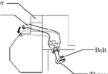 Thread take-up operating lever W1326QLoosen the hexagon socket head cap screw of the thread take-up operating lever and adjust the take-up movable range. Tighten it securely afterwards.• Are the needle bar clamp and the top dead center stopper positioned correctly? Thread take-up operating lever W1326QLoosen the hexagon socket head cap screw of the thread take-up operating lever and adjust the take-up movable range. Tighten it securely afterwards.• Are the needle bar clamp and the top dead center stopper positioned correctly? |
| ■Stitches cannot be made. • Is the needle attached properly?• Is the timing of the needle and rotary hook correct? | ||
Electrical Section
Cautions
- Be sure to turn off the power of the machine and unplug the power cord before checking cable connections.
- When you check connection of the cables as instructed in this manual, also check connection and continuity between connectors.
- Carry out items described in the "Measures" section in order of appearance.
- Some checks and replacement works can be conducted only by repair people. In such cases, contact your dealer.
| Symptom Measures | |
| The machine does not operate even if the power is turned on. | • Is the power cord of the machine plugged in?→Plug in the power cord.• Isn't the emergency stop switch locked?→Unlock the emergency stop switch.• Is the connector at the side of the control box connected?→Connect it after checking the connector name.• Is the connector in the control box connected?→Connect it after checking the types and colors of the connectors.• Isn't the fuse on the side of the control box blown?• Is the fuse on the PCB in the control box blown?→Replace the fuse with a new one. If the fuse is blown again, something is faulty. Check to see if the wiring is correct. Replace the control box with a new one. |
| An overtravel error occurs. • Is the frame within the cap frame area?→Move the frame within the cap frame area and turn on the power.• Check to see if the signal of the X area sensor turns ON and OFF in PORT test mode.→When the signal does not change, refer to the block diagram showing the cable connections and check to see if connection from the X area sensor to the main PCB is proper. Replace the X area sensor with a new one. | |
| The needle stop position error occurs. | • Is the pulley manually turned and out of the stop angle?→Turn the pulley, adjust the needle at the stop position, and reset the error.• Check the signal of the stop position sensor in the encoder test mode.→Refer to the adjustment or cable connection block diagram and check connection from the needle position detention sensor to the main PCB. Replace the needle position detection sensor with a new one. |
| The needle bar case lock error occurs. | • Is the INDEX motor rotating?→If not, refer to the block diagram showing the cable connections and check to see if connection from the INDEX motor to the main PCB is proper.Check the resistance values of pins 1 and 3 and pins 4 and 6 at the connector section of the INDEX motor. The normal resistance value is approximately 6.6 .→If it is not normal, replace the INDEX motor with a new one. Also replace the drive PCB with a new one.• Manually turn the color change pulley.→If it is abnormally heavy, adjust the color change mechanism and the needle cap case.• Replace the needle bar position sensor with a new one.• Replace the I/O PCB 0 with a new one. |
| X-axis or Y-axis home position detection error occurs. | • Was the XY carriage moving?→If so, refer to the block diagram showing the cable connections and check to see if connection from the X and Y area sensor to the drive PCB is proper.• Was the XY motor rotating?→If so, check the XY carriage mechanism.• If the XY motor is not rotating, refer to the cable connection block diagram and check to see if connection from the XY motor to the drive PCB is proper. |
| The thread breakage error frequently occurs although thread is not broken. | • Enter the CASE test mode and turn the thread breakage sensor pulley corresponding to each needle bar of the head with which this error occurs while switching the needle bar from number 1 in ascending order and check to see that the red LED on the head blinks.→If there is no problem, lower the thread breakage sensitivity value of the machine controller. (The standard value is 0.)• Check connection from the thread breakage sensor PCB to the thread tension base PCB if it does not blink.• Replace the thread breakage sensor PCB with a new one. |
| The X-axis motor connector connection error occurs. | • Refer to the block diagram showing the cable connections and check the connection from the two X motors (one X motors in four head models) on the left and right to the main PCB. |
| The main shaft motor lock error occurs. | • Enter the encoder signal mode and manually turn the main shaft pulley.→If it is abnormally heavy, the main shaft mechanism is faulty.• Does the main shaft motor rotate at all when the error occurs?→If it does not rotate at all, check fuse F1, F2 and F3 on the power supply PCB in the control box. Refer to the block diagram showing the cable connections and check to see if connection from the main shaft motor to the drive PCB is proper.• Manually turn the main shaft pulley in the encoder signal test mode and check to see if the stop position signal and encoder signal are proper.→If either of the signals does not change, refer to the block diagram showing the cable connections and check to see if connection from the encoder and stop position sensor to the power supply PCB is proper. |
| ERROR A8 frequently occurs. • In the encoder signal test mode, manually turn the main shaft pulley and check to see that the stop position signal is correct.→If the signal does not change, refer to the cable connection block diagram and check to see if connection from the stop position sensor to the power supply PCB is proper. | |
| Thread trimming motor home position error occurs. | • Is lint clogged between the travelling blades?→Remove it.• Is the thread trimming motor operating?→If so, refer to the block diagram showing the cable connections and check to see if connection from the thread breakage sensor to the main PCB is proper. Also adjust the thread breakage sensor PCB.(Refer to "Replacing thread breakage sensor PCB.)• If it is not operating, refer to the block diagram showing the cable connections and check to see if connection from the thread trimming motor to the main PCB is proper.• Check to see if connection from connector P3 of the main PCB to connector P9 of the power supply PCB in the control box is proper.• Check fuse F6 on the power supply PCB in the control box.→If it is blown, replace it with a new one. If it is blown again, replace the power supply PCB. |
| Power frequency error occurs. • Check | whether the connector P2 of the power supply PCB is fallen out. |
| Wiper out error occurs. • Does the wiper on the error head remain projected?→If the wiper is tangled with a thread, remove it. If the wiper does not return smoothly, adjust it.• Enter the solenoid test mode and operate the wiper motor. Check the icon on the panel.→If the icon is not reversed white, check to see if connection from the wiper sensor to the head PCB is proper. Replace the wiper sensor with a new one. Replace the head PCB with a new one. | |
| Embroidering data buffer empty, embroidering start error occurs.NOTEThis error may rarely occur according to your PC's performance.If it occurs, check the items shown on the left. | • Has the IF cable come off?• Has the RS cable on the PC come off?• Is the PC or machine controller down?→Reboot the PC or machine controller.• Are any other software programs running on the PC?• Replace the IF cable. |
| Main shaft rotation speed error occurs. | • Enter the encoder signal test mode and manually turn the main shaft pulley.→If it is abnormally heavy, the main shaft mechanism is faulty.• Refer to the block diagram showing the cable connections and check to see if connection from the main shaft motor to the drive PCB is proper. |
| Cooling fan motor stops.Exhaust fan motor stops.When all three fans in the control box stop | • Refer to the block diagram showing the cable connections and check to see if connection from connector P4 of the power PCB in the control box to connector P3 and P4 of the drive PCB .• Check fuse in the fuse holder at the side of the control box.→If it is blown, replace it with a new one. |
| Power voltage upper or lower limit error occurs. | • Is the tap voltage in the control box (connector connection) adjusted to the power voltage of the area where the machine is used?→ If not, switch the connector connection.• Check the input voltage values in the power/voltage check test mode.Measure the power supply voltage with the tester and compare them.→ If the voltage value is significantly out of the normal range ( ± 5v or more), calibrate it with the voltage calibration in the PC test mode.• When you cannot enter the test mode because this error frequently occurs, set the voltage to a relatively high value with the machine controller if it is E-D2 and to a relatively low value if it is E-D3 to avoid errors. Check and calibrate the voltage in the test mode.• Check to see the connection of connector P2 of the power supply PCB to connector P10 of the power supply PCB in the control box is proper.• Is the power supply abnormally low because a machine with a large capacity (compressor and the like) is used?→ Change the power to the other system. Use a stabilizer.• Replace the power PCB with a new one. Replace the main PCB with a new one. |
| Only a certain head does not operate. | • Is the head out of action with either the head switch or the machine controller?• Refer to the block diagram showing cable connections and check to see that other cables are connected to the head switch PCB and the head PCB and the head PCB properly. |
| Jump motor does not operate. • Check to see if connection from the jump motor to connector P11 and P12 of the head PCB is proper. | |
| Wiper motor does not operate. | • Check to see if connection from the wiper motor to connector P8 and P9 of the head PCB is proper.• Replace the head PCB with a new one. |
Personal Computer Section
| Trouble Check Point | ||
| Check these points once again | ■The power lamp does not light up when the computer power switch is turned on. | • Is the cable correctly plugged in the computer?• Is the AC line live? |
| ■The display does not light up when the computer power switch is turned on. | • Is the display power lamp on?• Is the display's cable correctly connected?• Is the display's contrast correctly adjusted? | |
| ■"Windows" cannot be started. • Is a floppy | disk inserted? | |
| ■"Windows" can be started but the embroidery software cannot. | • Is the selection of other icons possible?• Is the selected icon correct?• Can you double-click more quickly? | |
| ■The window does not open though the machine power is turned on? | • Is the cable to the machine and the interface board correctly connected?• Is the interface board attached properly?(Refer to Page 2-12.)• Is the correct COM port selected?(Refer to Page 6-7.) | |
| ■The screen changes when the mouse is not operated for a while. | • The screen saver is preset.Invalidate this function on the control panel screen.Do not validate the power-saving function. | |
| ■The screen of the editor,the explorer or the production report disappears during operation. | • The machine controller screen was clicked so that the current screen is hidden behind it.Move the mouse to the bottom of the screen and select the program (editor,explorer,or production report). | |
| ■Colors set for a design and threads are not available. | • The number of colors is set to 256.Increase the number to 65000 or more on the control panel screen. |
Chapter 13
Connection and Installation of Optional Equipment
1. Attaching Bobbin Winder
![[4] [14] [2] [8] [7] [5] [6] [3] [1] [11] [10] [13] [10] [15] [16] [9] W1327Q](/content/2026/05/1004755/images/8efbd5a3140131c277d135fc237f23d07fbd21148efe82c38472d4916aef2f98.jpg)
- Mount two pieces of bobbin stand L [2] on the thread winder stay [1] with nut 4 [10].
- Mount the thread winder assembly (set) [3] on the thread winder stay [1] with the tightening screw [11].
- Mount the thread guide [4] with the drilling bolt set 6 × 20 [14] and nut 6 [13].
- Mount the spool shaft B [5] and pan [6], spool mat [7], and spool cushion [8] with nut 5 [15] and spring washer [16].
- Insert the thread winder harness [9] in the 2P (No. 6) connectors on the rear of the control box.
■Winding lower thread
![[3] [5] [8] [3] [7] [2] [1] [6] [4] [9]](/content/2026/05/1004755/images/d7e2a4bf3675861e772f67256483bd1a31aaf26ff375721a05628891c9d69834.jpg)
W1328Q
-
Turn the power switch on.
-
Set the bobbin [1] in the bobbin winder shaft [2].
-
Put the thread through the thread guide [3].
-
Wind the thread around the bobbin [1] several times in the direction of the arrow.
-
Press the bobbin hold [4].
If the thread cannot be wound evenly, loosen the screw [5] and move the thread guide [3] right and left for adjustment.
In order to wind more threads around the bobbin, loosen the thread [6] and move the bobbin hold [4].
- After winding is finished, pull out the bobbin from the bobbin winder shaft and trim the thread using the thread trimmer [7].
- If the thread is wound too tight and comes off from the tension disk, loosen the knob [8]. If the thread is too loose, tighten the knob [8].
- If the circuit protector [9] functions, the bobbin winder motor does not rotate. Leave it for a while for cooling. Then press the circuit protector [9]. (The thread does not come out when the motor is not cooled enough.)
INSTRUCTION MANUAL
BROTHER INDUSTRIES, LTD. http://www.brother.com/
15-1. Naeshiro-cho, Mizuho-ku, Nagoya 467-8561, Japan. Phone: 81-52-824-2177

- SAFETY INSTRUCTIONS
- Safety indications and their meanings
- Symbols
- Notes on safety
- DANGER
- CAUTION
- Environmental requirements
- Installation
- Maintenance and inspection
- Warning labels
- Injury caution display
- High temperature caution display 9 High temperature caution display
- Ground mark
- Direction of operation
- Protecting data in floppy disks
- Explanation of models
- Configuration of this manual
- Chapter 1 An Introduction of Embroidery Machine
- Chapter 2 Preparation of Embroidery Machine
- Chapter 3 Embroidering Procedures
- Chapter 4 Selecting and Transferring Embroidery Data
- Chapter 5 Editing Embroidery Data
- Chapter 6 Embroidering
- Chapter 7 Operation of Machine
- Chapter 8 Creating Production Report
- Chapter 9 Maintenance
- Chapter 10 Adjustment
- Chapter 11 List of Error Codes
- Chapter 12 Troubleshooting
- Chapter 13 Connection and Installation of Optional Equipment
- Contents
- Chapter 1 Preparation of Embroidery Machine
- Changing Data....5-23
- Group 5-26
- Merge 5-28
- Saving Data 5-30
- Viewing Pattern Information 5-32
- Printing Data....5-33
- Functions (Command Reference)....6-2
- Description of Screen....6-5
- Settings before Turning On the Machine....6-6
- Settings after Turning Power On 6-9
- Setting the Machine....6-25
- Embroidering 6-50
- Moving the Home Position 6-52
- Step-forward/Step-back 6-53
- Moving Embroidery Position 6-57
- Centering Pattern 6-58
- Saving Data 6-59
- Test 6-60
- Running Other Programs....6-61
- Operating Procedures 7-2
- Machine Stop....7-3
- Permission for Hoop Movement....7-4
- Measures against Thread Breakage....7-5
- Jog Embroidering....7-8
- Hoop Feed Position 7-9
- Area Check 7-10
- Jog Switches....7-11
- Functions (Command Reference)......8-2
- Description of Screen....8-3
- Displaying Report 8-4
- Setting Display Items....8-12
- Save As CSV....8-18
- Printing Production Report....8-19
- Copying Report Data 8-20
- Chapter 11 Error code list
- Chapter 1
- An Introduction of
- Embroidery Machine
- Software
- 2-1 Necessary Systems
- 2-2 Configuration of Software
- Program Functions
- Relationship among Programs
- 2-3 Notes on use
- 2-4 Help
- 2-5 Basic Operation of Software
- How to Use the Mouse
- Click
- ■ Double-click
- Drag
- Names of Screen Components
- ■ Menu
- ■ Tool bar
- ■ Scroll bar, scroll box, and scroll arrow
- ■ Status bar
- Selection of Menu
- Names of Machine Components
- Installation
- !DANGER
- 2-1 Transportation of Machine
- 2-2 Installation of Machine
- 2-3 Preparation of Needle Bar Case
- 2-4 Mounting of Table
- ■ For embroidering with flat hoop/sash frame (upper position)
- 2-5 Mounting of Cotton Stand
- 2-6 Lubrication to Needle Bar Case
- 2-7 Connection of Personal Computer to Machines (for connecting 4 sets)
- 2-8 Connection of Power Supply
- ■ Uninterruptive power supply
- 2-9 Grounding
- 2-10 Installation of Software
- Preparation for Embroidering
- 3-1 Upper Threading
- 3-2 Replacement of Bobbin
- ■ Removing bobbin case
- ■ Replacing bobbin
- Put a new bobbin in the bobbin case.
- 3-3 Replacing and Selecting Needle
- ■ Selecting needle
- ■ Removing needle
- ■ Attaching needle
- 3-4 Attachment of Embroidery Hoop and Frame
- ■ Tubular square hoop
- ■ Holder base (optional)
- Attaching the holder base frame
- Attaching the holder base
- ■ Sash frame (optional)
- Attaching the sash frame
- 3-5 Adjustment of Thread Tension
- ■ Adjustment of upper thread
- \* Correct adjustment
- ■ Adjustment of tension spring
- ■ Lower thread tension
- Chapter 3
- Embroidering Procedures
- Functions of Operation Panel
- Operation Panel
- ■Canceling errors
- Switches at Machine Heads
- ■Stop switch
- ■Start switch
- ■STEP BACK/FWD switch
- Lamps and switches on the thread tension stand
- ■ Thread tension stand lamp
- ■Thread tension stand switch
- Flowchart of Preparation for Embroidering
- Run the Software
- Turn on the Machine Power
- Register the Machine Name
- Retrieve the Embroidery Data
- Start Embroidering
- Functions (Command Reference)
- Description of Screen
- Creating a Directory
- Transferring data
- Transferring DST and DSB data
- Transferring data on a network
- If no image appears:
- Copy
- Select from Menu
- Drag Data
- Moving Data
- Deleting Data
- Recreate an icon
- Select All
- Renaming Data
- Finding Data
- Finding Files With Wildcard Characters
- ■Using (?)
- ■Using "\*"
- Adjusting Screen Display
- Reading Data in Floppy Disk
- Reading DOS Format Data
- Converting the Non DOS format data
- Viewing Files
- ■Viewing Details
- ■Viewing Icon
- ■Preview and Refresh
- Select data to read and click [OK].
- Reading Data in Paper Tape
- Settings for Data Reading
- Writing Data in DST Format
- Viewing Pattern Information
- Chapter 5
- Editing Embroidery Data
- Opening Embroidery Data
- Setting Display
- Centering
- Zoom
- Zoom In
- Zoom Out
- Range
- Fit to window
- Needle Penetration
- Embroidering Start/End
- Trim and pause
- Microstitch
- Needle Bar and Speed Range
- Change of display color
- Select an arbitrary color from basic colors.
- Select a color by clicking on the color chart or by inputting a value, and click [OK].
- Input the name of the color and click [OK] when [User] is selected in step 4.
- Changing needle bar allocation
- Setting the range
- Thread Color
- Tool bar
- Select [Tool Bar] from View menu.
- Status Bar
- Select [Status Bar] from View menu.
- Back to Previous Status
- Undo
- Redo
- Editing
- Rotate
- Horizontal Flip
- Vertical Flip
- Point Symmetry
- Repeat
- Margin setting with [Auto setting] selected
- Resize
- Delete Stitch
- Insert or Delete Code
- Select [Insert or delete code] from the Edit menu.
- Select the movement method of needle position.
- Move the needle position to the desired position.
- Insert or delete the code.
- Insert Lock Stitch
- Changing Data
- Changing Start
- Select [Start] from Change menu.
- Changing End
- Select [End] from Change menu.
- Mask
- Group
- Setting Group for Repetition
- Selecting from Menu
- Merge
- Saving Data
- Save
- Save As...
- Printing Data
- When the Power to the Machine is Off
- When the Power to the Machine is On
- Settings before Turning On the Machine
- Displaying the Tool Bar
- Displaying the Status Bar
- Upgrading the Version of Interface Board
- Reset Interface Board
- Communication Port
- Language
- Settings after Turning Power On
- Zoom In Specified Range
- Whole Pattern
- Grid
- Hoop
- Hoop position fine adjustment
- Setting Needle Bar
- Changing display colors
- Setting Ranges
- Changing all ranges
- Changing individual range
- Grid Setting
- Background color
- Renaming Machine
- Viewing Machine Information
- Design Information
- Setting Window Display
- Minimizing and Aligning Windows
- Minimize Window Size
- Arrange Icons
- Changing window size
- Copying Data to Other Machines
- Click [OK].
- Configuration
- Click [OK].
- Upgrading the Machine Program
- Setting the Machine
- Needle Bar
- Same Speed Range
- Pause
- Stopping all the needle bars temporarily
- Resetting temporary stop of all the needle bars
- Speed Range
- Head Operation Suspend
- Hoop Feed Position
- Embroidery Area
- Embroidery Hoop
- Select [Embroidery Hoop] and the type from Settings menu.
- ■The following shows the screen example with the frame selected.
- Thread Trimming
- Thread Breakage Sensor
- Automatic Step Back
- Automatic Hoop Feed
- End of embroidery
- Mending
- Click [OK] when the items are set.
- Adjust
- Select [Adjust] from Settings menu.
- When setting is complete, click [OK].
- Driving shaft
- Activate escape with pause
- Short stitch speed reduction
- Thin / Thick Material
- Area Trace
- Trace with needle No. 1
- Default Settings
- Select [Default Settings] from Settings menu.
- Click [OK].
- Show Setting
- ■The following items are shown:
- Select [Show Setting] from Settings menu.
- After checking, check [OK].
- Load Setting
- Save Setting
- Load Hoop
- Select [Load hoop] from Settings menu.
- Select the folder and click [Open].
- Embroidering
- Starting Embroidering
- Click .
- Press the button.
- Canceling
- Moving the Home Position
- Step-forward/Step-back
- Entering in the Step-forward/Step-back Mode
- Canceling step-forward/step-back
- Setting Step-forward/Back Distance or Timing
- Stepping Forward/Back
- # #
- Specifying the Value
- Resuming Embroidering
- Moving Embroidery Position
- Centering Pattern
- Test
- Running Other Programs
- ■The following programs can be started:
- Select [Embroidery Data Explorer independently] or [Embroidery Data Editor independently] from Tool menu.
- Selecting [Embroidery Data Edit Individual Start]
- Operating Procedures
- 1-1 Power Source
- 1-2 Preparation for Embroidering
- Machine Stop
- 2-1 Stopping the Machine
- 2-2 Emergency Stop of the Machine
- 2-3 Resetting Emergency Stop
- Permission for Hoop Movement
- Measures against Thread Breakage
- 4-1 Remedies
- 4-2 Mending
- Manual operation of the mending
- Jog Embroidering
- Hoop Feed Position
- Press
- Area Check
- 7-1 External Tracing
- 7-2 Automatic Hoop Movement in Area
- Jog Switches
- 8-1 Hoop Movement to Start Position
- 8-2 Inching Mode during Embroidering (Forcible Hoop Movement)
- Displaying Report
- Display Example of Details
- Display Example of Thread Breakage Information on Needle Bar
- Display in graph
- Display Example of Thread breakage Information in Pattern
- Display Contents
- Display in text
- Display Example of Output Information
- Details of reason for stoppage
- Display Example of Total Output Information
- Setting Display Items
- General
- ■Collate
- ■Storage
- Details
- ■Main items to be displayed
- ■Sub items to be displayed
- Thread Breakage Information on Needle Bar
- Thread Breakage Information in Pattern
- Output Information
- ■Reason for stoppage
- Total Output Information
- ■Target machine
- Recess Time Setting
- ■Total recess time
- ■Total maintenance time
- Save As CSV...
- Printing Production Report
- Page Setup
- Select [Page setup] from the File menu.
- Select [Print] from File menu or click
- Copying Report Data
- Cleaning
- 1-1 Cleaning and Lubrication of Rotary Hook
- 1-2 Cleaning of Needle Plate
- Oiling
- 2-1 Head
- 2-2 Lower shaft
- Greasing
- 3-1 Cam grooves
- 3-2 Lower gear
- 3-3 Driving shaft
- 3-4 Needle bar flip-up mechanism
- 3-5 Feed Guide Section
- Procedure
- Adjusting Needle Bar Height
- Attachment and Adjustment of Rotary Hook
- Adjustment of Presser Foot Height
- Thread Wiper Adjustment
- Electrical Section
- Cautions
- Personal Computer Section
- Chapter 13
- Connection and Installation of Optional Equipment
- Attaching Bobbin Winder
- ■Winding lower thread
Brand : BROTHER
Model : BE-1204C-BC
Category : Uncategorized